Portable engine operated machine

a technology of engine operated machines and operated machines, which is applied in the direction of machines/engines, mechanical equipment, combustion air/fuel air treatment, etc., can solve the problems of large space needed to store the large engine operated machine, restrictions on the aesthetic design of the engine operated machine, and complex construction, etc., and achieve efficient ventilation

Inactive Publication Date: 2006-12-12
HONDA MOTOR CO LTD
View PDF2 Cites 19 Cited by
  • Summary
  • Abstract
  • Description
  • Claims
  • Application Information

AI Technical Summary

Benefits of technology

[0008]The cooling air passage serves also as the hand space which is formed in an end wall of the case. The hand space is a depressed part of the case. Therefore, the carrying handle does not need to be projected from the case or needs to be only slightly projected from the case. Thus, the carrying handle does not occupy a very large space and is not prominent, whereby the engine operated machine can be formed in a small size. Consequently, the engine operated machine can be stored in a small space, the hand space does not spoil the aesthetic appearance of the engine operated machine, and the engine operated machine has an excellent aesthetic appearance. Since the cooling air passage serves also as the hand space, restrictions on the design of the case are fewer than those on the design of a case separately provided with a cooling air passage and a hand space. The hand space formed in the end part or wall of the case facilitates carrying the engine operated machine. The carrying handle is exposed to and cooled by the cooling air flowing through the cooling air passage while the engine operated machine is in operation. Therefore, the carrying handle is not heated and can be gripped safely.
[0010]The carrying handle can be easily gripped by putting a hand on the lower end part of the carrying handle. Since the cooling air passage is formed in a labyrinthine shape by the carrying handle having the lower end part and the depressed part, the cooling air passage has a simple construction. Since the enclosed space in the case communicates with the outside space by means of the labyrinthine cooling air passage, the leakage of noise from the case can be effectively reduced without increasing the manufacturing cost of the engine operated machine.
[0012]Since a human hand can be put on various parts of the carrying handle extending in a wide lateral range to grip the carrying handle, parts, suitable for gripping, of the carrying handle can be selectively gripped, which facilitates carrying the engine operated machine. The inlet of the cooling air passage can be formed in a large area without spoiling the aesthetic appearance of the engine operated machine, the cooling air flowing through the laterally wide cooling air passage into the case suppresses the stagnation of air in the case and, consequently, the engine and the working machine can be efficiently cooled.
[0014]When two cooling air passages are thus formed, hot air heated by the engine and the working machine in the state of hot soak immediately after the stop of the engine and rising upward by convection can easily flow to the outside through the cooling air passages. Thus the natural ventilation of the interior of the case is promoted and the cooling of the engine and the working machine immediately after the stop of the engine is promoted.
[0016]Since the cooling air flows into the case through the cooling air passages on the opposite sides of the engine and the working machine, the cooling air of comparatively low temperatures lower than that of the cooling air that flows into the case through one cooling air passage flows around the engine and the working machine. Thus, the engine and the working machine can be efficiently cooled. The pair of cooling air passages are able to discharge hot air from the case immediately after the stop of the engine more efficiently than one cooling air passage. Thus the interior space of the case can be efficiently ventilated.

Problems solved by technology

A large space is needed to store the large engine operated machine.
Thus the carrying handles place restrictions on the aesthetic design of the engine operated machine.
When the cooling air passage is formed in a labyrinthine shape to suppress the outward propagation of noise generated by the engine operated machine through the cooling air passage, the case inevitably has complex construction and increases the cost of the engine operated machine.

Method used


Image

  • Portable engine operated machine
  • Portable engine operated machine
  • Portable engine operated machine

Examples


Embodiment Construction

[0032]Preferred embodiments of the present invention will be described with reference to FIGS. 1 to 10.

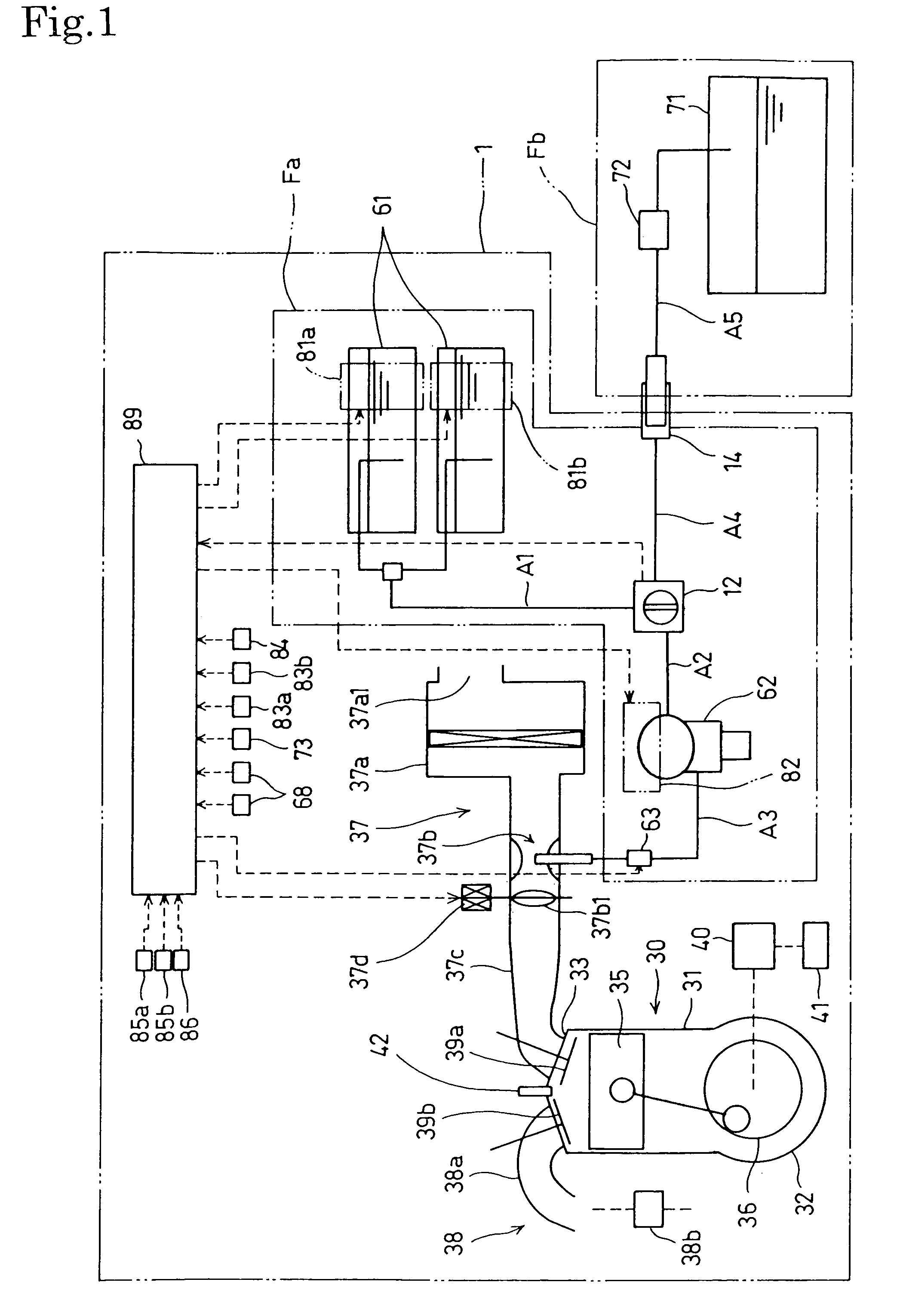
[0033]FIGS. 1 to 7 show an engine generator 1, namely, a portable engine operated machine, in a first embodiment of the present invention. Referring to FIG. 1, the engine generator 1 can be connected to an external fuel system Fb.

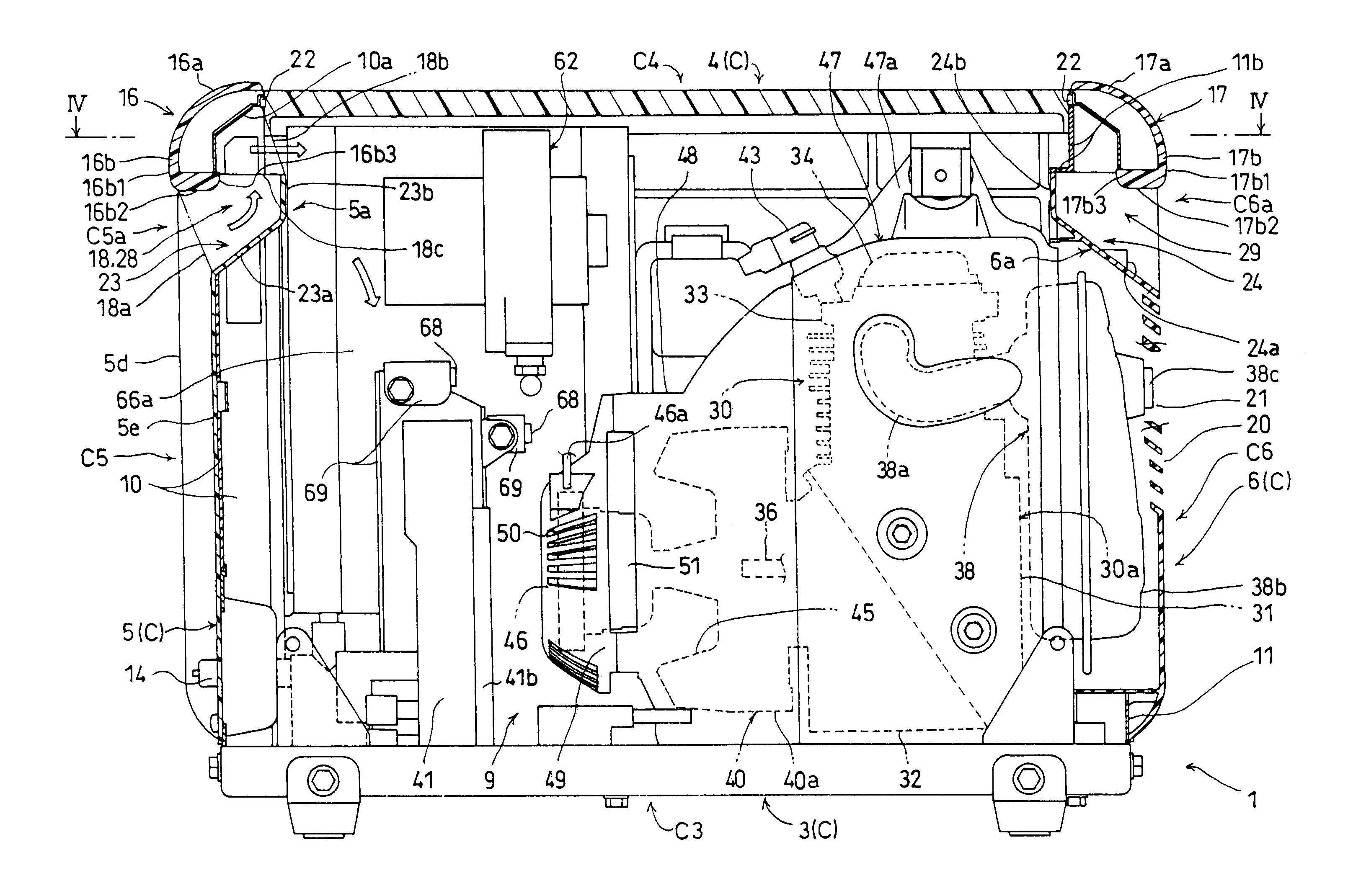
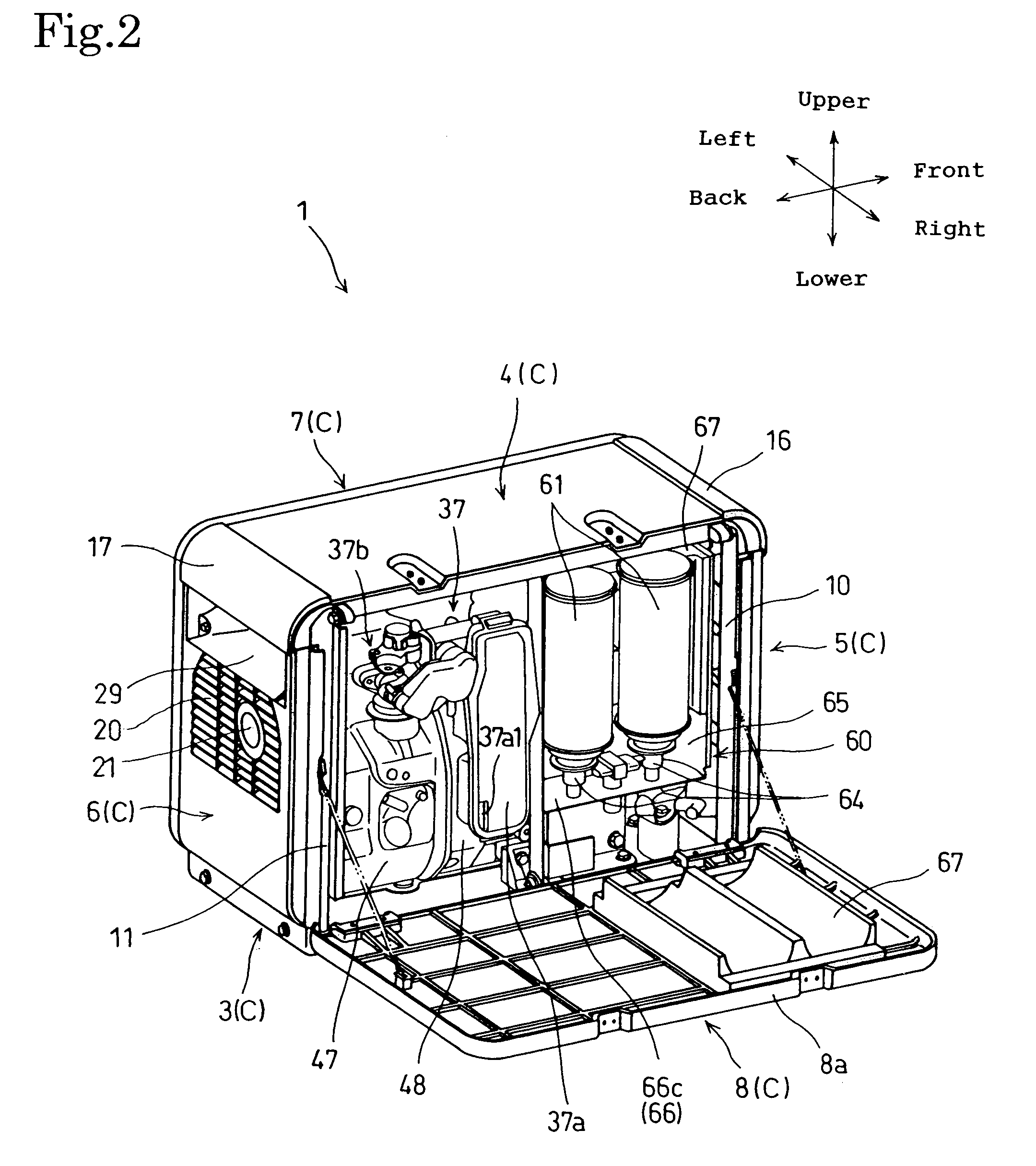
[0034]Referring to FIGS. 2 and 3, the engine generator 1 includes a box-shaped case C in the form of a rectangular body, a pair of carrying handles 16 and 17 combined with the case C, a combustion engine 30, such as a gas engine, a fuel supply system Fa for supplying a fuel gas to the engine 30, an electric generator 40, namely, a working machine, to be driven for operation by the engine 30, a power control unit 41 for controlling power generated by the generator 40, and an electronic control unit (ECU) 89 for controlling the engine 30 and the fuel supply system Fa. The engine 30, the fuel supply system Fa, the generator 40, the power control unit 41 and t...


PUM


Abstract

A portable engine generator has a box-shaped case defining an internal space for holding an engine and an electric generator to be driven by the engine. The case is provided with carrying handles. The portable engine generator is provided with a cooling air passage through which fresh air as cooling air flows into the internal space while the engine is in operation. An inward depressed part is formed in a front cover of the case on the side of the internal space with respect to the carrying handles. The carrying handles and the inward depressed part define the cooling air passage. The cooling air passage serves as a hand space into which human hand is inserted to grip the carrying handles.

Description

BACKGROUND OF THE INVENTION[0001]1. Field of the Invention[0002]The present invention relates to a portable engine operated machine having an engine, a working machine driven by the engine, a box-shaped case housing the engine and the working machine and a carrying handle.[0003]2. Description of the Related Art[0004]There are a variety of engine operated machines. Each of those engine operated machines is built by combining an engine and a working machine to be driven by the engine. An engine generator having an electric generator as a working machine is leisure and emergency equipment used widely as a temporary or emergency power supply. The engine operated machine has an engine, a working machine and a box-shaped case housing the engine and the working machine to suppress noise propagation during operation. The case is provided with a cooling air passage through which cooling air flows into the case to cool the engine and the working machine. A prior art portable engine operated m...

Claims


Application Information

Patent Timeline
Patent Type & Authority Patents(United States)
IPC IPC(8): F02B77/00
CPCF01P5/06F02B63/04
Inventor SUGIMOTO, YASUHIROYAGUCHI, TADAHIROTAKEMURA, KAZUHITOKOBAYASHI, TAKAO
Owner HONDA MOTOR CO LTD
Why Eureka
Try Eureka