Loop systems and methods of using the same for conveying and distributing thermal energy into a wellbore

a loop system and thermal energy technology, applied in the direction of borehole/well accessories, drinking water installation, insulation, etc., can solve the problems of oil not being heated adequately, reducing the quality of steam being injected into the wellbore, and difficult recovery of oil from some subterranean formations, so as to reduce the viscosity of oil and improve the recovery

Active Publication Date: 2006-12-12
HALLIBURTON ENERGY SERVICES INC
View PDF49 Cites 184 Cited by
  • Summary
  • Abstract
  • Description
  • Claims
  • Application Information

AI Technical Summary

Benefits of technology

[0007]According to some embodiments, methods of treating a wellbore comprise using a loop system to heat oil in a subterranean formation contacted by the wellbore. The loop system conveys steam down the wellbore and returns condensate from the wellbore. A portion of the steam in the loop system may be injected into the subterranean formation using one or more injection devices, such as a thermally-controlled valve (TCV), disposed in the loop system. Alternatively, only heat and not steam may be transferred from a closed loop system into the subterranean formation. The condensate returned from the wellbore may be re-heated to form a portion of the steam being conveyed by the loop system into the wellbore. Heating the oil residing in the subterranean formation reduces the viscosity of the oil so that it may be recovered more easily. The oil and the condensate may be produced from a common wellbore or from different wellbores.

Problems solved by technology

Many reservoirs containing vast quantities of oil have been discovered in subterranean formations; however, the recovery of oil from some subterranean formations has been very difficult due to the relatively high viscosity of the oil and / or the presence of viscous tar sands in the formations.
Until the temperature of these elements reach the boiling point of water, at least a portion of the steam produced by the boiler condenses, reducing the quality of the steam being injected into the wellbore.
As such, the oil might not be heated adequately to stimulate production of the oil.
In addition, the condensate might cause water logging to occur.
Further, the steam is typically injected such that it is not evenly distributed throughout the well bore, resulting in a temperature gradient along the well bore.
Areas that are hotter and colder than others, i.e., hot spots and cold spots, thus undesirably form in the subterranean formation.
The cold spots lead to the formation of pockets of oil that remain immobile.
Consequently, the steam bypasses a large portion of the oil residing in the formation, and thus fails to heat and mobilize the oil.

Method used


Image

  • Loop systems and methods of using the same for conveying and distributing thermal energy into a wellbore
  • Loop systems and methods of using the same for conveying and distributing thermal energy into a wellbore
  • Loop systems and methods of using the same for conveying and distributing thermal energy into a wellbore

Examples


Embodiment Construction

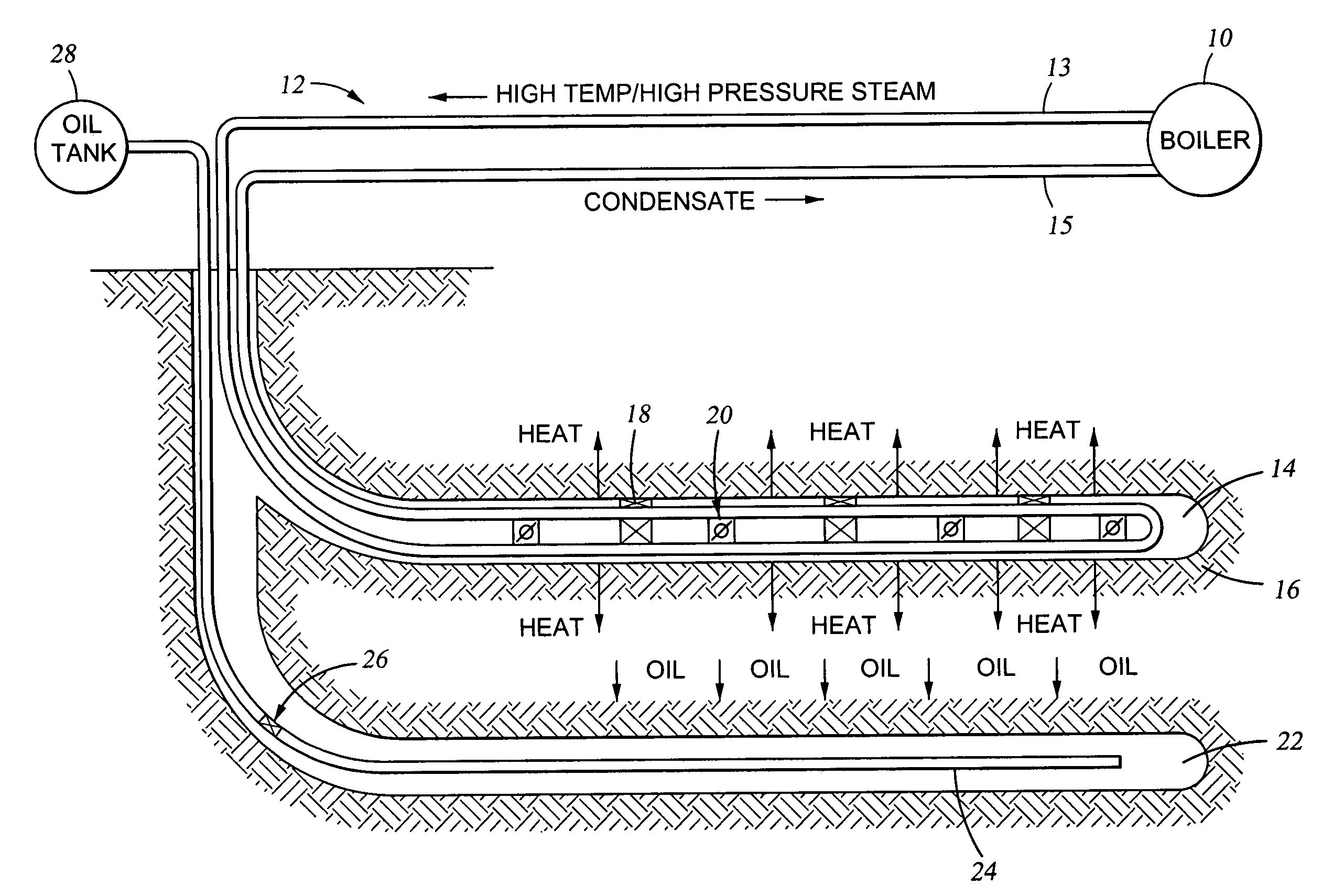
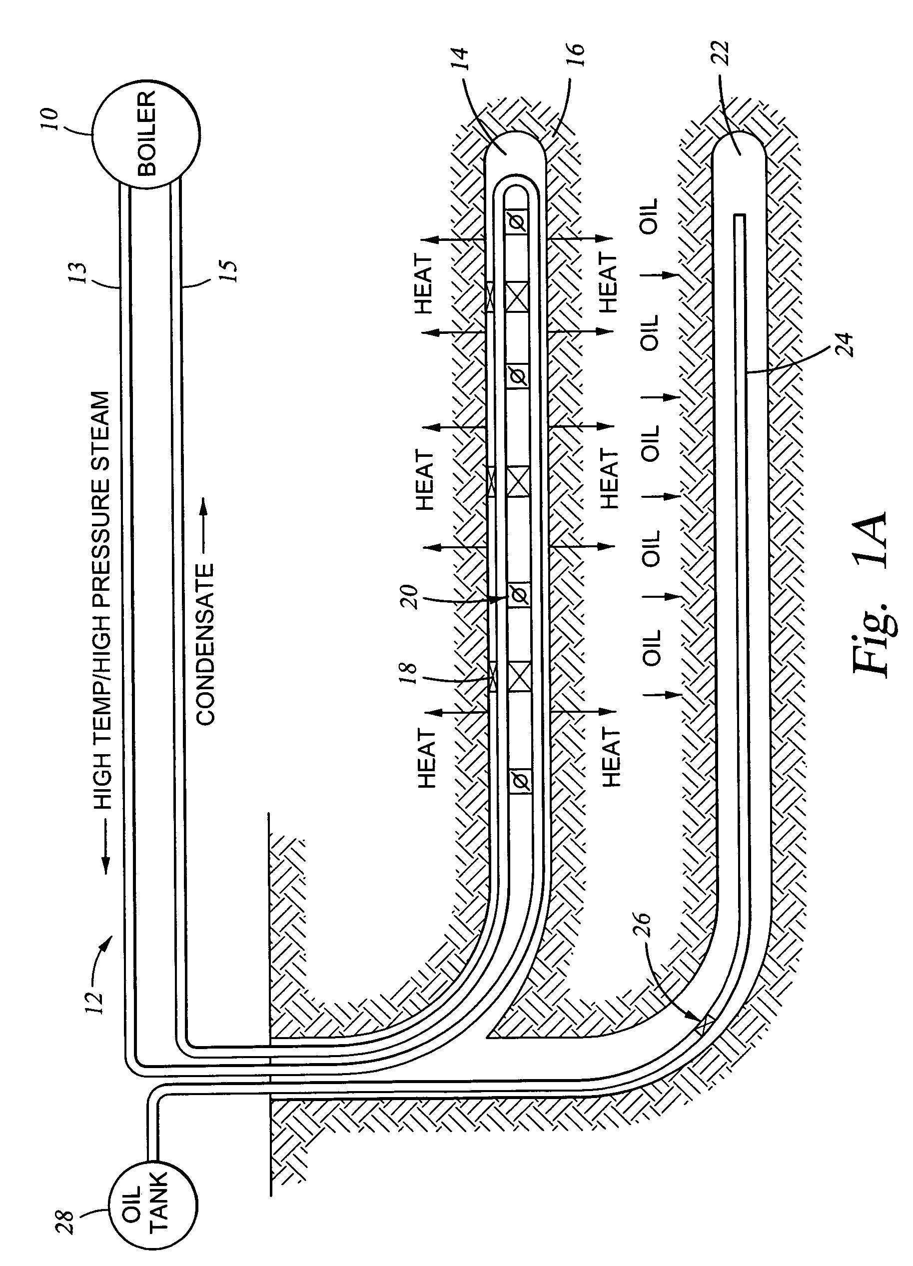
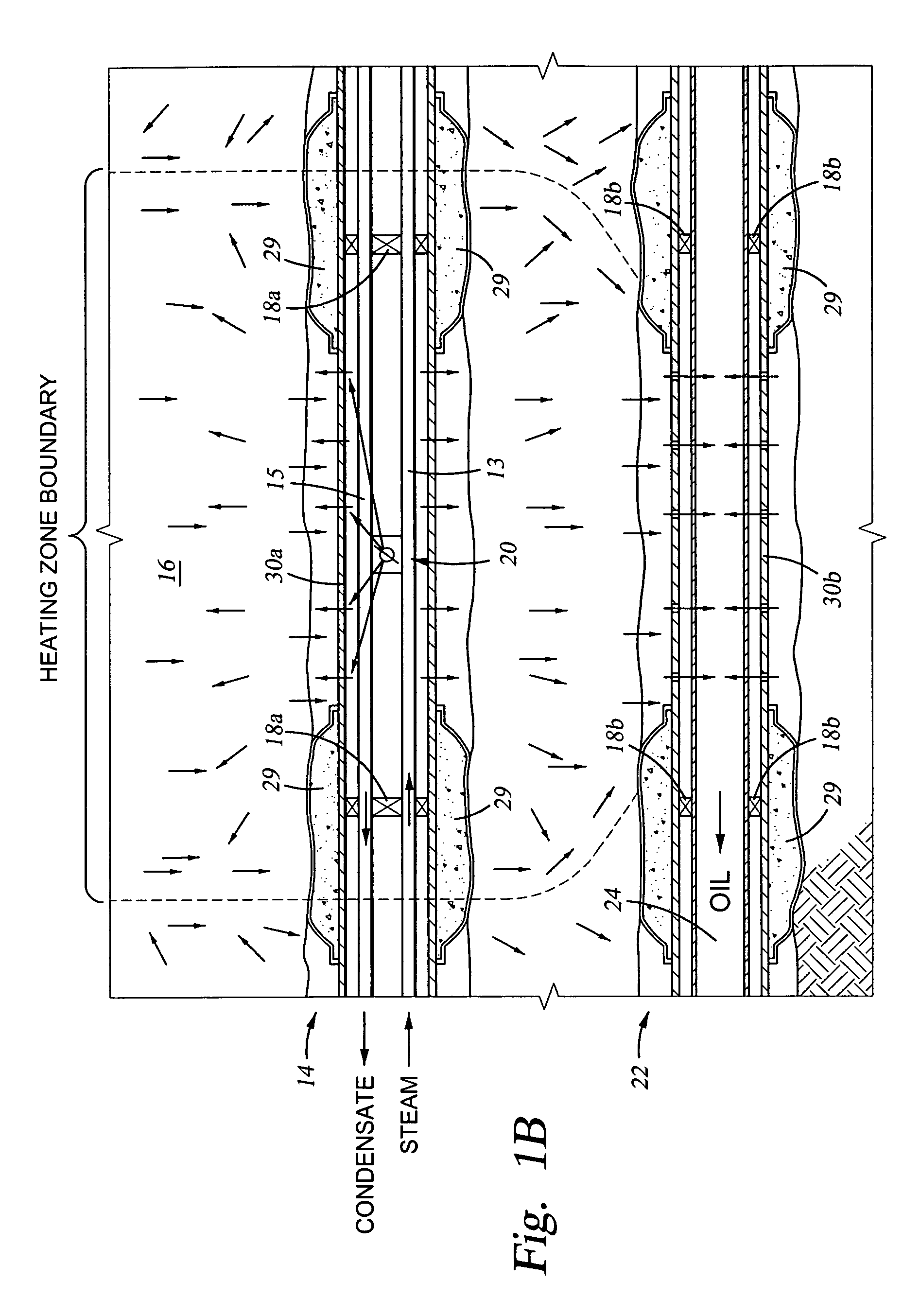
[0019]As used herein, a “loop system” is defined as a structural conveyance (e.g., piping, conduit, tubing, etc.) forming a flow loop and circulating material therein. In an embodiment, the loop system coveys material downhole and return all or a portion of the material back to the surface. In an embodiment, a loop system may be used in a well bore for conveying steam into a wellbore and for returning condensate from the wellbore. The steam in the wellbore heats oil in a subterranean formation contacted by the wellbore, thereby reducing the viscosity of the oil so that it may be recovered more easily. The loop system comprises a steam loop disposed in the wellbore that includes a steam boiler coupled to a steam injection conduit coupled to a condensate recovery conduit. The steam loop may optionally comprise control valves and / or injection devices for controlling the injection of the steam into the subterranean formation. When control valves are disposed in the steam loop, the loop ...


PUM


Abstract

Systems and methods are provided for treating a wellbore using a loop system to heat oil in a subterranean formation contacted by the wellbore. The loop system comprises a loop that conveys a fluid (e.g., steam) down the wellbore via a injection conduit and returns fluid (e.g., condensate) from the wellbore via a return conduit. A portion of the fluid in the loop system may be injected into the subterranean formation using one or more valves disposed in the loop system. Alternatively, only heat and not fluid may be transferred from the loop system into the subterranean formation. The fluid returned from the wellbore may be re-heated and re-conveyed by the loop system into the wellbore. Heating the oil residing in the subterranean formation reduces the viscosity of the oil so that it may be recovered more easily.

Description

CROSS-REFERENCE TO RELATED APPLICATIONS[0001]The subject matter of this patent application is related to the commonly owned U.S. patent application Ser. No. 10 / 681,020 entitled “Thermally-Controlled Valves and Methods of Using the Same in a Well Bore,” filed on Oct. 6, 2003 and incorporated by reference herein.FIELD OF THE INVENTION[0002]This invention generally relates to the production of oil. More specifically, the invention relates to methods of using a loop system to convey and distribute thermal energy into a wellbore for the stimulation of the production of oil in an adjacent subterranean formation.BACKGROUND OF THE INVENTION[0003]Many reservoirs containing vast quantities of oil have been discovered in subterranean formations; however, the recovery of oil from some subterranean formations has been very difficult due to the relatively high viscosity of the oil and / or the presence of viscous tar sands in the formations. In particular, when a production well is drilled into a s...

Claims


Application Information

Patent Timeline
Patent Type & Authority Patents(United States)
IPC IPC(8): E21B43/24
CPCE21B43/2408E21B43/2406
Inventor STEELE, DAVID JOEMCGLOTHEN, JODY R.BAYH, III, RUSSELL IRVING
Owner HALLIBURTON ENERGY SERVICES INC
Why Eureka
Try Eureka