Automobile slide adjuster

a technology for sliding adjusters and automobiles, applied in the field of sliding adjusters, can solve the problems of increasing the number of components, requiring a lot of manufacturing time, and a large number of component parts, and achieves the effects of reducing the number of component parts and assembling work, and stabilizing the sliding resistan

Inactive Publication Date: 2006-12-12
DELTA KOGYO CO LTD
View PDF21 Cites 30 Cited by
  • Summary
  • Abstract
  • Description
  • Claims
  • Application Information

AI Technical Summary

Benefits of technology

[0015]It is accordingly an objective of the present invention to provide a highly reliable automobile slide adjuster of a simple construction, which is capable of reducing the number of component parts or the assembling work and in which the sliding resistance is stabilized.
[0020]The above-described construction requires no rolling elements at an upper portion of the upper and lower ails, making it possible to reduce the number of component parts and the assembling work. Furthermore, the elongated opening formed along the lower edge of each upward protrusion provides the upward protrusion with vertical elasticity. Accordingly, even if dimensional variations of the lower rail or the upper rail exist, the vertical elasticity of the upward protrusion can absorb such dimensional variations and, hence, the sliding resistance is stabilized and the productivity is enhanced.
[0021]Also, the upper portion of the lower rail is partially held in sliding contact with the upper portion of the upper rail via only the upward protrusions, making it possible to further stabilize the sliding resistance and provide a highly reliable automobile slide adjuster of a simple construction.

Problems solved by technology

Accordingly, this slide adjuster requires many component parts and a lot of time for the manufacture thereof.
However, the provision of the elastic elements results in an increase in the number of component parts and requires a time-consuming assemblage.
In the slide adjuster as disclosed in Document 4, 5 or 6, vertical and horizontal looseness is eliminated by the projections formed on the lower rail or the upper rail, but this slide adjuster involves a problem in that the sliding resistance cannot be readily stabilized due to variations in the size of the upper or lower rail.
Furthermore, a high dimensional accuracy is required, resulting in a reduction in productivity.

Method used


Image

  • Automobile slide adjuster
  • Automobile slide adjuster
  • Automobile slide adjuster

Examples


Embodiment Construction

[0036]This application is based on an application No. 2003-324957 filed Sep. 17, 2003 in Japan, the content of which is herein expressly incorporated by reference in its entirety.

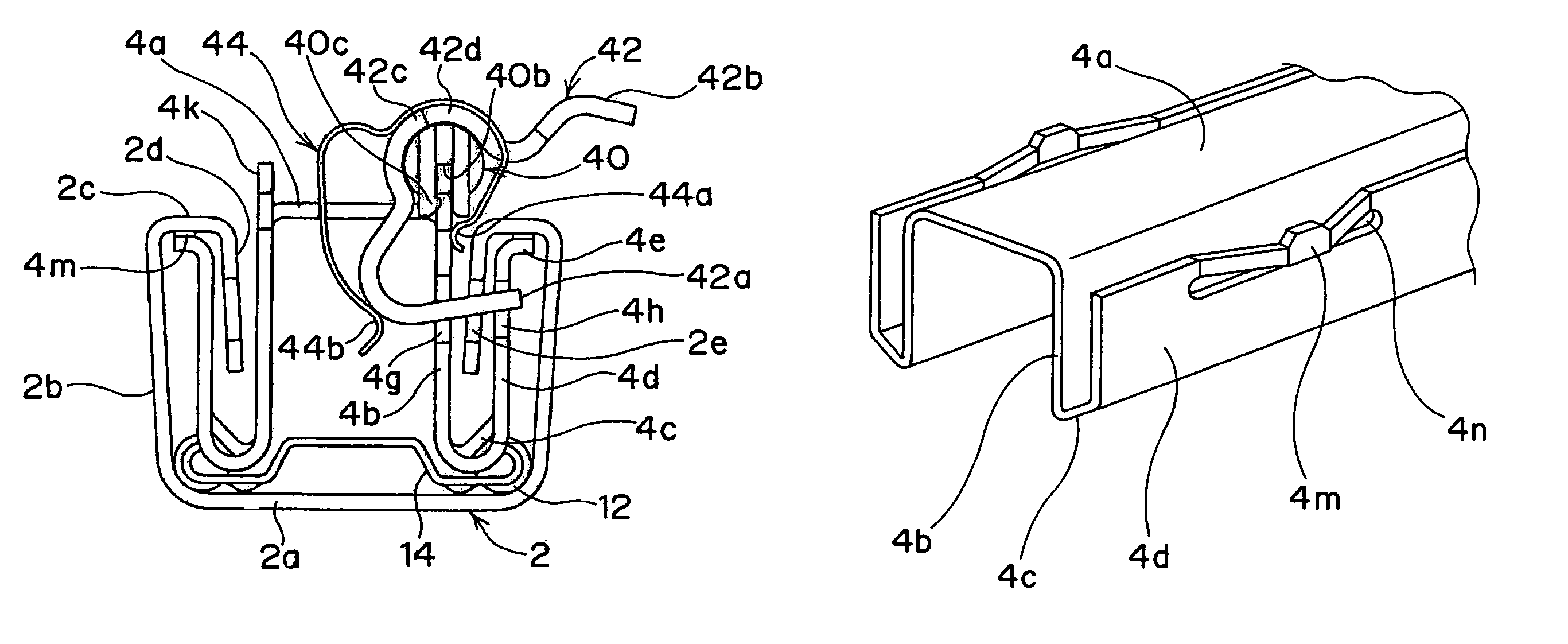
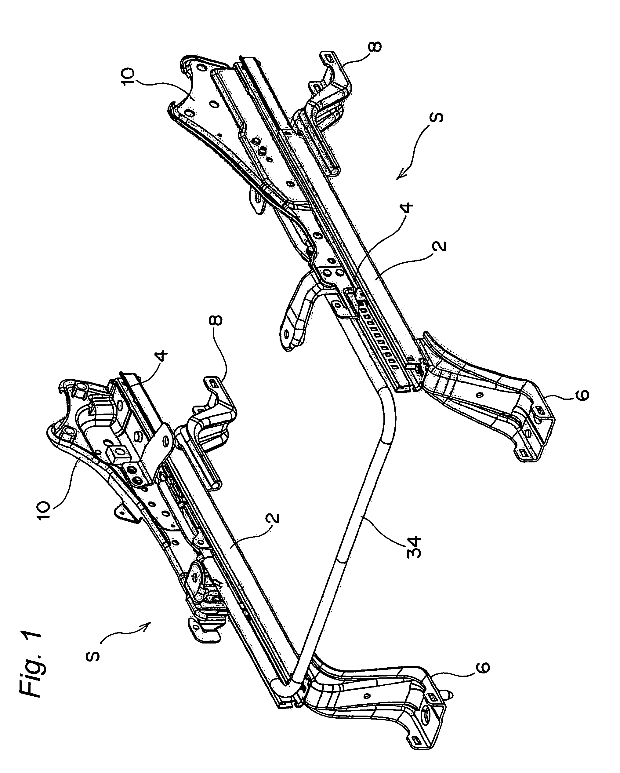
[0037]Referring now to the drawings, there is shown in FIG. 1 an automobile slide adjuster S embodying the present invention, which is disposed on each side of a seat (not shown) for use in adjusting the position of the seat in the longitudinal direction of a vehicle body. Because the pair of slide adjusters S are symmetric with respect to the longitudinal centerline of the seat, only one of them that is positioned on the right-hand side as viewed from a seat occupant is explained hereinafter.

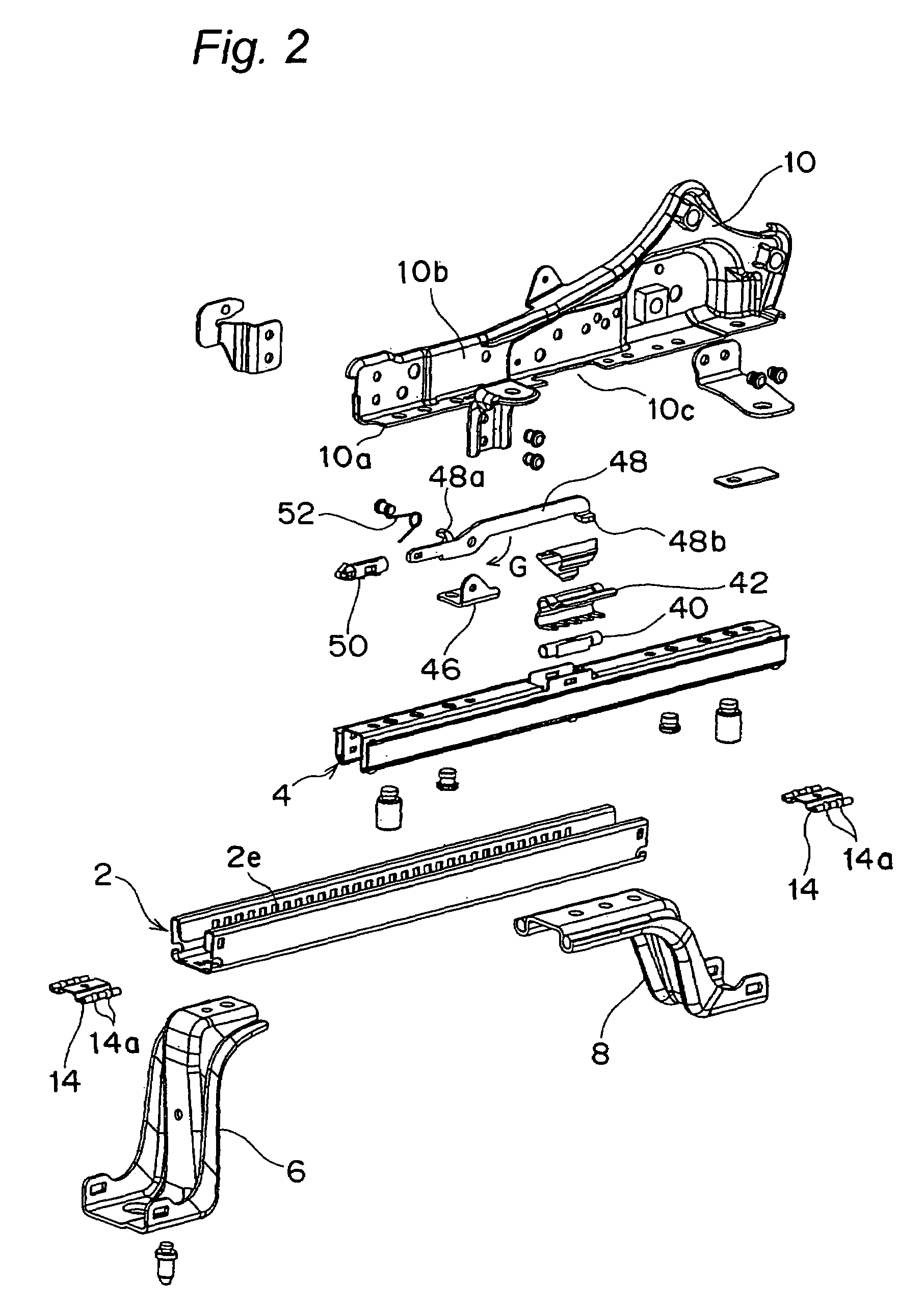
[0038]As shown in FIGS. 1 and 2, the automobile slide adjuster S includes a lower rail 2 and an upper rail 4 mounted thereon so as to be slidable relative thereto in the longitudinal direction thereof. The lower rail 2 is rigidly secured to a vehicle floor via front and rear brackets 6, 8, while a side frame 10 forming...


PUM


Abstract

An automobile slide adjuster includes a lower rail to be secured to a vehicle body and an upper rail slidably mounted on the lower rail. A plurality of rolling elements are disposed between the upper and lower rails at a lower portion thereof. The upper rail has a plurality of upward protrusions formed on an upper portion thereof and also has an elongated opening formed along a lower edge of each of the plurality of upward protrusions. The upward protrusions are held in sliding contact with a portion of the lower rail.

Description

BACKGROUND OF THE INVENTION[0001]1. Field of the Invention[0002]The present invention relates to a slide adjuster for use in adjusting the position of an automobile seat in a longitudinal direction of a vehicle body.[0003]2. Description of the Related Art[0004]Automobile slide adjusters generally include a lower rail and an upper rail mounted thereon so as to be slidable relative thereto. Some conventional automobile slide adjusters include a plurality of rolling elements such as, for example, rollers, balls, or the like interposed between the lower rail and the upper rail to reduce the sliding resistance (see Document 1). Some conventional automobile slide adjusters include a plurality of elastic elements made of, for example, a resin interposed between the lower rail and the upper rail to eliminate clearances between the lower rail and the upper rail (see Document 2 or 3). Furthermore, some conventional automobile slide adjusters include a plurality of projections formed on the lo...

Claims


Application Information

Patent Timeline
Patent Type & Authority Patents(United States)
IPC IPC(8): F16M13/00B60N2/06B60N2/07B60N2/08
CPCB60N2/072B60N2/073B60N2/0818B60N2/0843B60N2/07
Inventor DANJO, YASUHARUIZUMI, YASUO
Owner DELTA KOGYO CO LTD
Why Eureka
Try Eureka