Contact lens and production method for contact lens

a production method and contact lens technology, applied in the field of contact lenses, can solve the problems of difficult to distinguish the front from the back, tedious handling, and difficulty in designing and manufacturing contact lenses in a series, and achieve the effect of efficient manufacturing

Inactive Publication Date: 2006-12-12
MENICON CO LTD
View PDF3 Cites 15 Cited by
  • Summary
  • Abstract
  • Description
  • Claims
  • Application Information

AI Technical Summary

Benefits of technology

[0015]In the series of contact lenses according to this mode, by adopting a novel element which had not been conceived of to date, namely, a common shape for the peripheral zone, it is now possible to use identical shape (including identical thickness dimension) for most of the peripheral zone regardless of which contact lens in the series is employed; and thereby to effectively and consistently provide the wearer with good wear comfort, stable position of the lens on the cornea, and vision regardless of the optical characteristics of the optical zone selected on a wearer-by-wearer basis, as well as realizing dramatic improvements in contact lens performance and reliability. Additionally, when a given wearer must change the diopter power of a contact lens as myopia or other abnormal refraction progresses, the discomfort associated with wear of a contact lens with a different diopter power may be reduced or avoided.
[0046]According to the method of the present invention, by changing the cutting pattern of the front surface optical zone in order to modify appropriately the shape of the front surface optical zone, it is a simple matter to establish various optical characteristics. Additionally, since areas other than the front surface optical zone, namely, the back surface optical zone, the back surface peripheral zone, and the front surface peripheral zone, are all formed by means of molding, these are easy to manufacture. In particular, since optical characteristics are determined by the shape of the front surface optical zone, it is possible to standardize mold shape for contact lenses of which different optical characteristics are required, so that manufacturing cost may be improved. Additionally, as compared to the case where both the front surface optical zone and the front surface peripheral zone are formed by cutting, the fact that only the front surface optical zone is formed by cutting makes it easier to control the cutting tool, making possible further improvement in manufacturing cost and reduction in time required for manufacture.

Problems solved by technology

Meanwhile, if the peripheral zone of a contact lens is too thin, it becomes difficult for the lens to consistently hold its shape, and particularly in the case of a soft contact lens may make it difficult to distinguish the front from the back, which can pose a risk of problems in handling.
A resultant problem was that design and manufacture of contact lenses making up a series was tedious.
Additionally, research conducted by the inventors has shown that where contact lenses of series based on prior art design methods are provided, when diopter power differs among contact lenses of a given series, the thickness dimension of the peripheral zone 60 and mass associated therewith differ appreciably, which in some cases can result in differences in the movement of the contact lens over the cornea due to the action of the eyelid occurring with blinking, or the position of rest of the contact lens on the cornea due to the effect of gravity or the like, resulting in some instances in adverse effects on wear comfort and vision.
Research conducted by the inventors, however, has shown that the shape of the peripheral zone has significant effects on contact lens wear comfort and vision, and in particular that appreciable thickness of the peripheral zone including the front surface junction can result in appreciably impaired wear comfort owing to pressure applied by the eyelid and the like, as well as appreciable movement of the lens over the cornea by the eyelid during blinking, or a tendency of the lens rest position to shift vertically downward on the cornea due to the greater effect of gravity, or in other such problems.

Method used


Image

  • Contact lens and production method for contact lens
  • Contact lens and production method for contact lens
  • Contact lens and production method for contact lens

Examples


Embodiment Construction

[0049]In order to illustrate the invention more concretely, the embodiments of the invention are described in detail hereinbelow, making reference to the accompanying drawings.

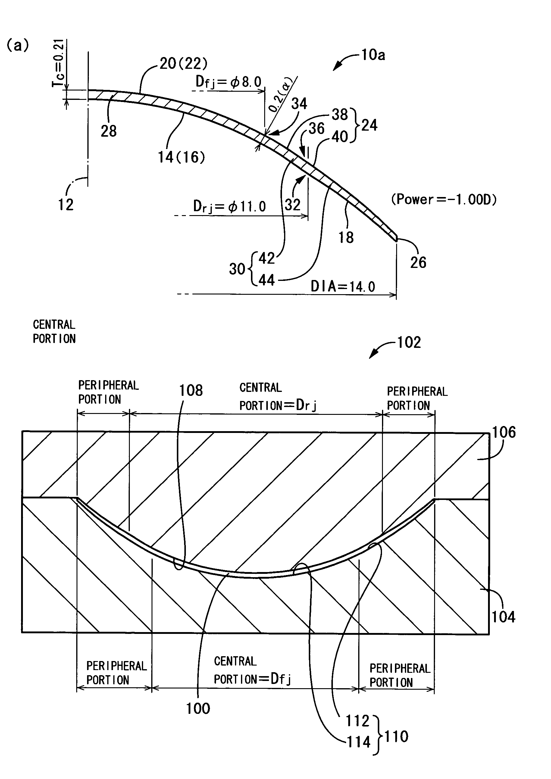
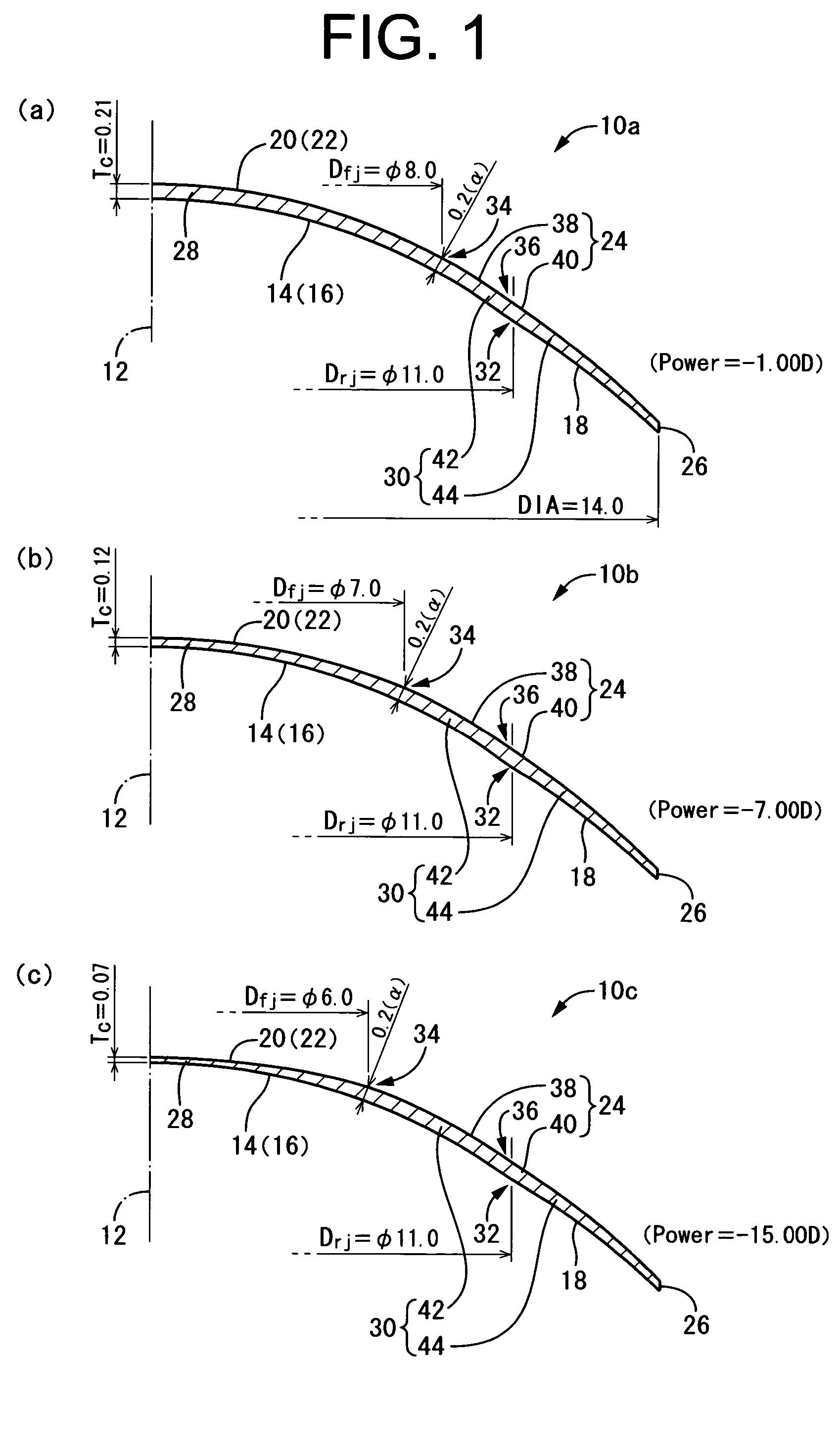
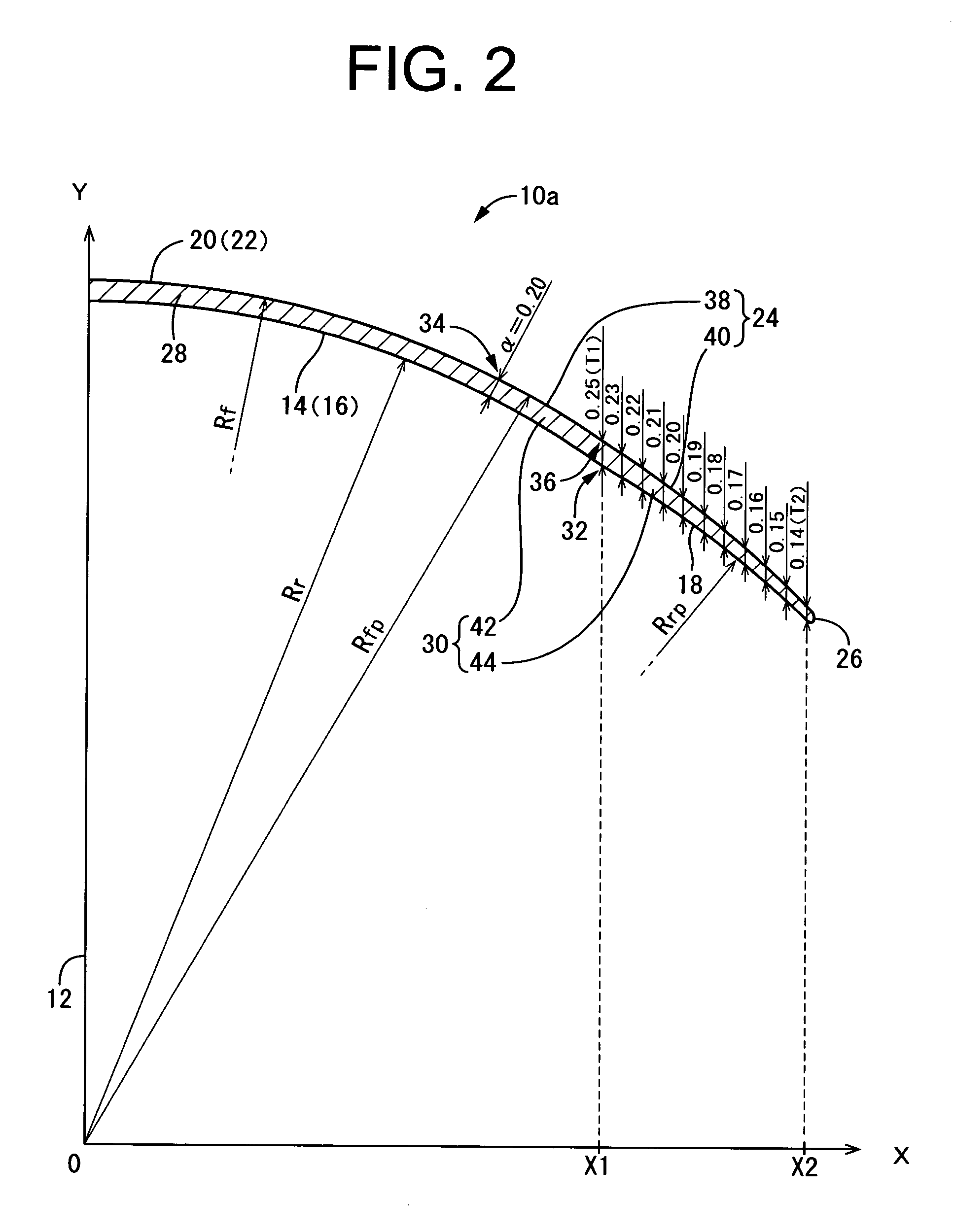
[0050]FIGS. 1(a), (b), and (c) depict as one embodiment of the invention a plurality of contact lenses 10a, 10b, 10c selected appropriately from a series of contact lenses. The series contact lenses are composed of combinations of a plurality of contact lenses whose optical zones have mutually different optical characteristics, for example, different refractive power (diopter power), and are provided to the wearer through suitable selection, from among the plurality of contact lenses, of one contact lens having optical characteristics appropriate for the wearer. The selection is made on the basis of the results of an examination of the optical system of the eye of the wearer by an ophthalmologist or other examiner. Here, the contact lenses 10a, 10b, 10c which are constituent elements of a series of contact len...


PUM


Abstract

It is an object of the invention to ensure in a series of contact lenses composed of an assorted plurality of contact lenses having mutually different optical characteristics such as refractive power or the like that each contact lens is capable of exhibiting advantageously and consistently a good wear comfort and tear fluid exchange. In order to attain the object, the present invention arranges each contact lens 10a, 10b, 10c making up the series contact lens designed and having mutually different optical characteristics in the optical zone, such that not only is a shape of the lens back surface 14 of the optical zone 28 identified, but a shape of the peripheral zone 30 is identified at least the outer peripheral zone 44 that contributes to wear comfort and tear fluid exchange.

Description

TECHNICAL FIELD[0001]The present invention relates generally to contact lenses of soft type or hard type. More particularly, the invention relates to contact lenses of novel structure appropriate to being provided as a series containing an assorted plurality of contact lenses having optical characteristics of various kinds, and capable of ensuring excellent wear comfort in every optical characteristics, and to a method of manufacturing such contact lenses.BACKGROUND ART[0002]One shape known in the art and widely employed to date for both soft contact lenses and hard contact lenses (hereinafter referred to collectively as “contact lenses”) is that depicted in FIG. 6(a), which has a back surface optical zone 50 formed in the center portion of the back surface of the lens and a back surface peripheral zone 52 formed along the outer circumference of this back surface optical zone 50, while having formed in the center portion of the front surface of the lens a front surface optical zone ...

Claims


Application Information

Patent Timeline
Patent Type & Authority Patents(United States)
IPC IPC(8): G02C7/04
CPCG02C7/028G02C7/04G02C2202/08
Inventor GOTOU, YUUJIMARUYAMA, KUNIO
Owner MENICON CO LTD
Why Eureka
Try Eureka