Assembling mechanism of discharge pipe for hermetic compressor and method thereof

a discharge pipe and hermetic compressor technology, applied in the direction of machines/engines, liquid fuel engines, positive displacement liquid engines, etc., can solve the problems of deformation of the upper cover, increase manufacturing costs, and reduce compressor performance and efficiency, so as to improve the assembling mechanism of the discharge pipe, improve the compressor performance, and prevent the effect of deformation

Inactive Publication Date: 2006-12-12
LG ELECTRONICS INC
View PDF12 Cites 19 Cited by
  • Summary
  • Abstract
  • Description
  • Claims
  • Application Information

AI Technical Summary

Benefits of technology

[0020]Therefore, an object of the present invention is to an assembling mechanism of a discharge pipe for a hermetic compressor and a method thereof, capable of improving performance of

Problems solved by technology

However, with the above assembling method of the discharge pipe of the scroll compressor in accordance with the conventional art, deformation is generated in the upper cover and the compression unit by indenting pressure in indenting the discharge pipe in the indenting hole of the muffler

Method used


Image

  • Assembling mechanism of discharge pipe for hermetic compressor and method thereof
  • Assembling mechanism of discharge pipe for hermetic compressor and method thereof
  • Assembling mechanism of discharge pipe for hermetic compressor and method thereof

Examples


first embodiment

[0055]FIGS. 5 to 8 are cross-sectional views showing assembling processes of a discharge pipe of a hermetic compressor in accordance with the present invention.

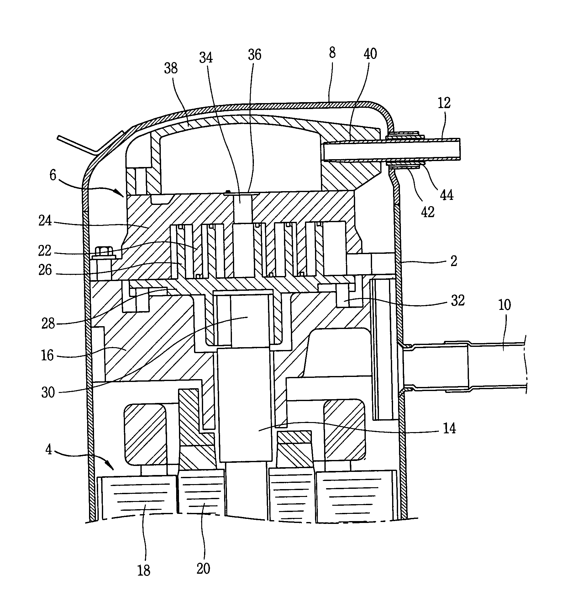
[0056]The assembling mechanism of the discharge pipe includes a first connection portion for welding / combining between the muffler 38 and the discharge pipe 12 and a second connection portion for welding / combining the upper cover 8 and the discharge pipe 12.

[0057]Here, in the first connection portion, an insertion hole 40 having the discharge pipe 12 inserted at a side of the muffler 38 is formed at a side of the muffler 38, and the discharge pipe 12 and the muffler 38 are welded / combined after inserting the discharge pipe 12 in the insertion hole 40.

[0058]In the second connection portion, a guide member 42 having an inner diameter larger than the outer diameter of the discharge pipe 12 is mounted at a side of the upper cover 8 so that the discharge pipe 12 can pass, an insertion member 44 is inserted in a gap between the dis...

second embodiment

[0068]FIG. 9 is a cross-sectional view showing an assembling mechanism of the discharge pipe of the hermetic compressor in accordance with the present invention.

[0069]The assembling mechanism of the discharge pipe in accordance with a second embodiment includes a first connection portion for connecting between the muffler 38 and the discharge pipe 12 by projecting welding after inserting the discharge pipe 12 in the insertion hole 40 of the muffler 38. In accordance with the second embodiment, the assembling mechanism includes a second connecting portion for welding / combining between the discharge pipe 12 and the upper cover 8 as shown in FIGS. 7 and 8.

[0070]Here, the muffler 38 is formed with a relatively small thickness, the muffler 38 and the discharge pipe 12 are combined by projection welding, and accordingly, a welding bead 52 is formed between the inner surface of the muffler 38 and the outer circumferential surface of the discharge pipe 12 inserted in the insertion hole 40 i...

third embodiment

[0072]FIG. 10 is a cross-sectional view showing an assembling mechanism of the discharge pipe of the hermetic compressor in accordance with the present invention.

[0073]The assembling mechanism of the discharge pipe in accordance with the third embodiment includes a first connection portion for welding / combining the discharge pipe with the muffler as shown in FIG. 9. In accordance with the third embodiment, the assembling mechanism includes a second connection portion in which the discharge pipe 12 is inserted inside the guide member 42 mounted in the upper cover 8 and the insertion member 60 is inserted in a gap between the guide member 42 and the discharge pipe 12 to be welded and combined together.

[0074]The first connection portion has an identical structure as the assembly structure described in the above embodiment.

[0075]The insertion member 60 of the second connection portion includes a first cylindrical portion 56 which is contacted on the inner circumferential surface of the ...


PUM


Abstract

An assembling mechanism of a discharge pipe and a method thereof, capable of preventing deformation of an upper cover and a compression unit generated in assembling the discharge pipe by improving assembling mechanism of the discharge pipe, thus to improve performance of the compressor. The assembling mechanism includes an upper cover on which a guide member having a discharge pipe inserted therein is mounted, a muffler in which an insertion hole having the discharge pipe inserted therein is formed, a first connection portion for welding/combining the discharge pipe and the muffler after inserting the discharge pipe in the insertion hole and a second connection portion for welding/combining the upper cover and discharge pipe.

Description

[0001]This Nonprovisional application claims priority under 35 U.S.C. §119(a) on Patent Application No(s). 2002-72091 filed in KOREA on Nov. 19, 2002, the entire contents of which are hereby incorporated by reference.BACKGROUND OF THE INVENTION[0002]1. Field of the Invention[0003]The present invention relates to an assembling mechanism of a discharge pipe and a method thereof and particularly, to an assembling mechanism of a discharge pipe for a hermetic compressor and a method thereof, capable of preventing deformation of parts generated in an assembling operation of a discharge pipe and improving efficiency of a compressor.[0004]2. Description of the Background Art[0005]Generally, a compressor can be formed by various types according to compressing methods, and as an air conditioning apparatus which is required to be smaller and lighter, a hermetic rotary compressor is mainly used.[0006]The hermetic compressor can be divided into a rotary compressor, reciprocating compressor, scro...

Claims


Application Information

Patent Timeline
IPC IPC(8): F04B39/12F04C23/00F04C18/02
CPCF04C23/008F04C18/0215F04C2240/30F04C2240/806Y10S417/902F04C18/02
Inventor CHEON, SUNG-HO
Owner LG ELECTRONICS INC
Why Eureka
Try Eureka