
Electric element having liquid metals

Active Publication Date: 2006-12-12
LOTES
View PDF11 Cites 23 Cited by
  • Summary
  • Abstract
  • Description
  • Claims
  • Application Information

AI Technical Summary

Benefits of technology

[0007]Comparing to prior arts, the liquid metals of the electric element of the present invention are used as a conductor for connecting two mental bodies so as to reduce significantly the impedance of the conductors and facilitate the signal transmissions.

Problems solved by technology

However, the metal slices have higher impedance.

Method used


Image

  • Electric element having liquid metals
  • Electric element having liquid metals
  • Electric element having liquid metals

Examples


Embodiment Construction

[0011]In order that those skilled in the art can further understand the present invention, a description will be described in the following in details. However, these descriptions and the appended drawings are only used to cause those skilled in the art to understand the objects, features, and characteristics of the present invention, but not to be used to confine the scope and spirit of the present invention defined in the appended claims.

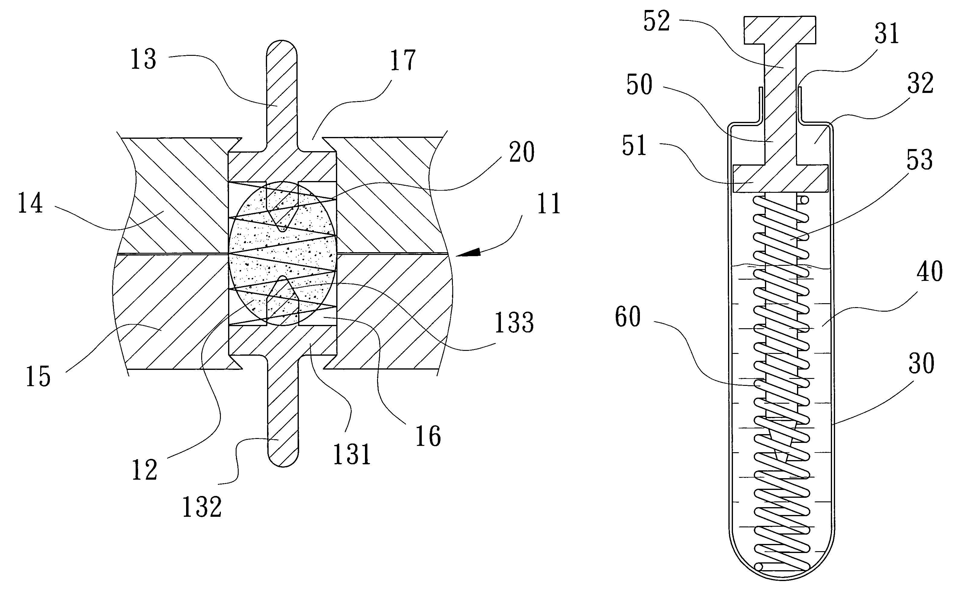
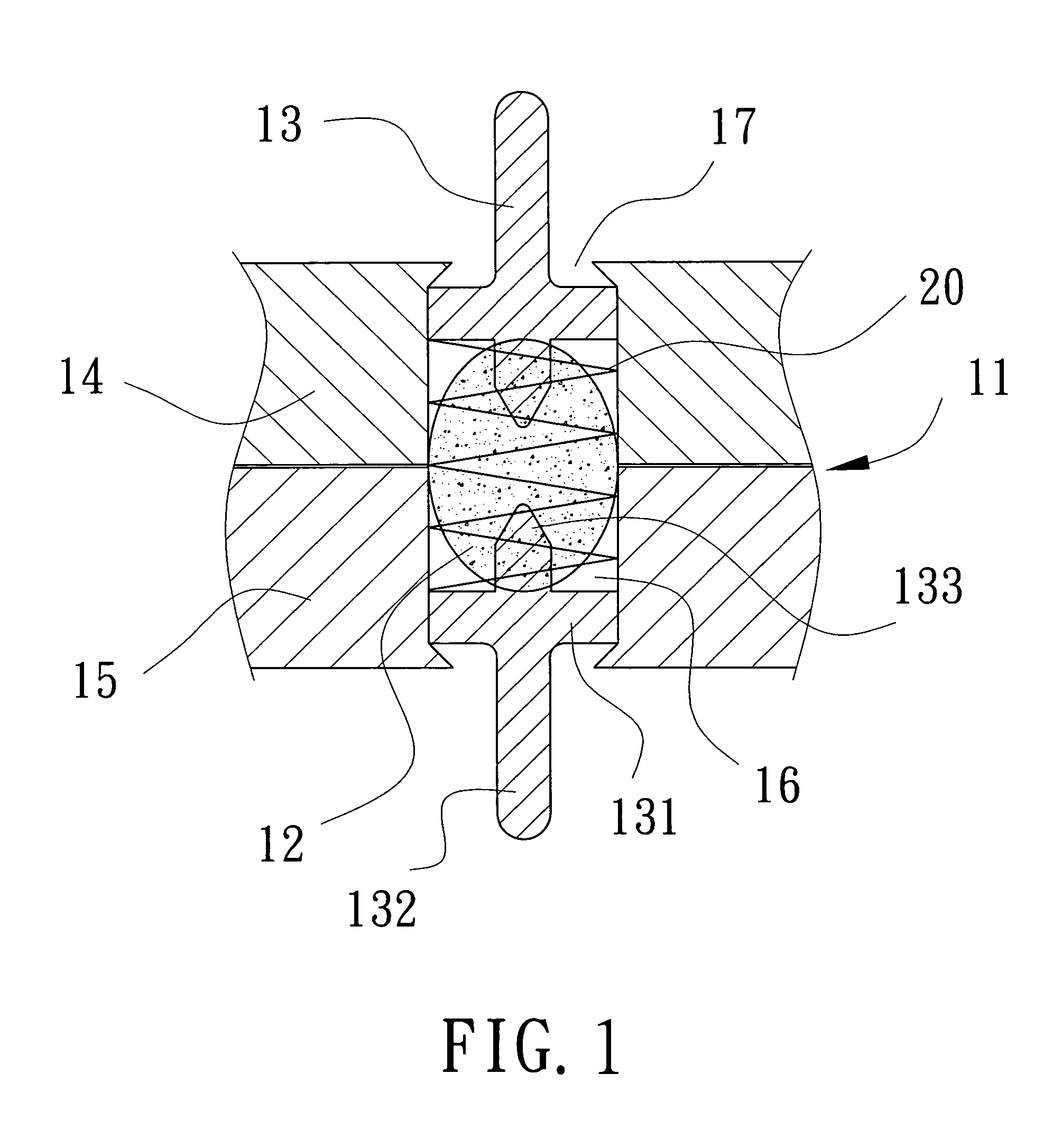
[0012]Referring to FIG. 1, an electric element of the present invention is used for connecting one circuit board to another circuit board. The electric element has insulating bodies 11. The insulating body 11 comprises an upper layer 14 and a lower layer 15. The upper layer 14 and the lower layer 15 are fixed each other and form a receiving space 16. The receiving space 16 is filled with liquid metals 12 of low impedance (such as: mercury). The capacity of the receiving space 16 is slightly larger than the volume of the liquid metals 12 so that th...


PUM


Abstract

An electric element for electric connection of two corresponding electric elements comprises: two conductors; and liquid metals with low impedance connecting to the two conductors. The two conductors keep in contact with the liquid metals at a situation of relative movement so as to reduce significantly the impedance of the conductors and facilitate the signal transmissions.

Description

BACKGROUND OF THE INVENTION[0001](a) Field of the Invention[0002]The present invention relates to electric elements, and particularly to an electric element with lower impedance.[0003](b) Description of the Prior Art[0004]Presently an electric element (such as: electric connector) comprises generally an insulating body and at least one conductor received in the insulating body. The conductor is usually made of punching metal slices. However, the metal slices have higher impedance. Particularly when the conductor is in mechanic contact with a corresponding electric element, a contact portion usually has higher impedance. In addition, a conductor should be bent for ensuring the conductor with better elasticity in many situations, so that the impedance of the conductor is increased.[0005]Therefore, it is necessary to develop a novel electric connector to overcome the above-mentioned defects.SUMMARY OF THE INVENTION[0006]Accordingly, the primary object of the present invention is to pro...

Claims


Application Information

Patent Timeline
IPC IPC(8): H01R12/00
CPCH01R3/08H01R13/2407H01R13/2414H01R13/2421H01R12/714
Inventor JU, TED
Owner LOTES
Learn More