

Power module
- Summary
- Abstract
- Description
- Claims
- Application Information
AI Technical Summary
Benefits of technology
Problems solved by technology
Method used
Image

Examples
first embodiment
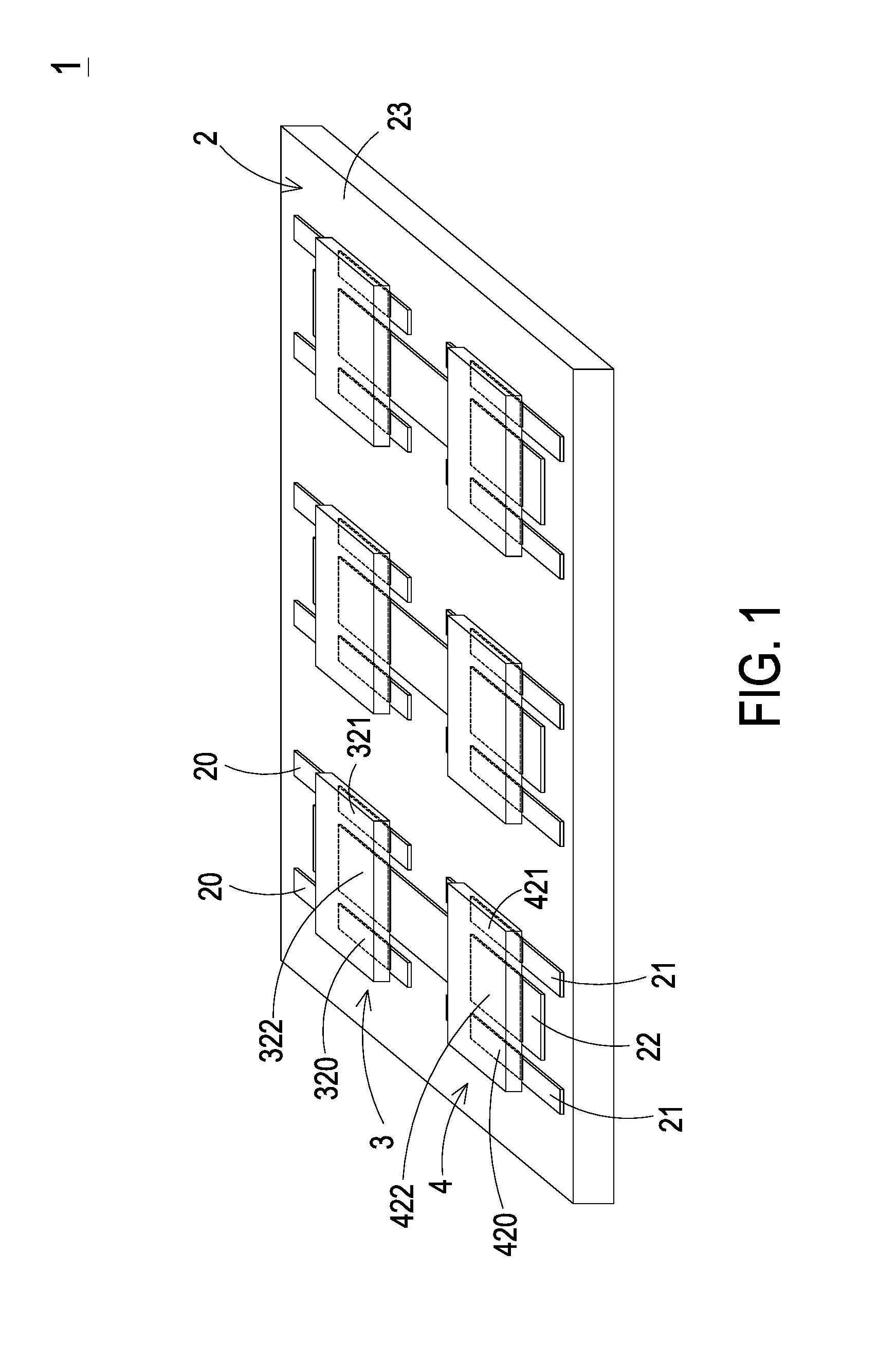
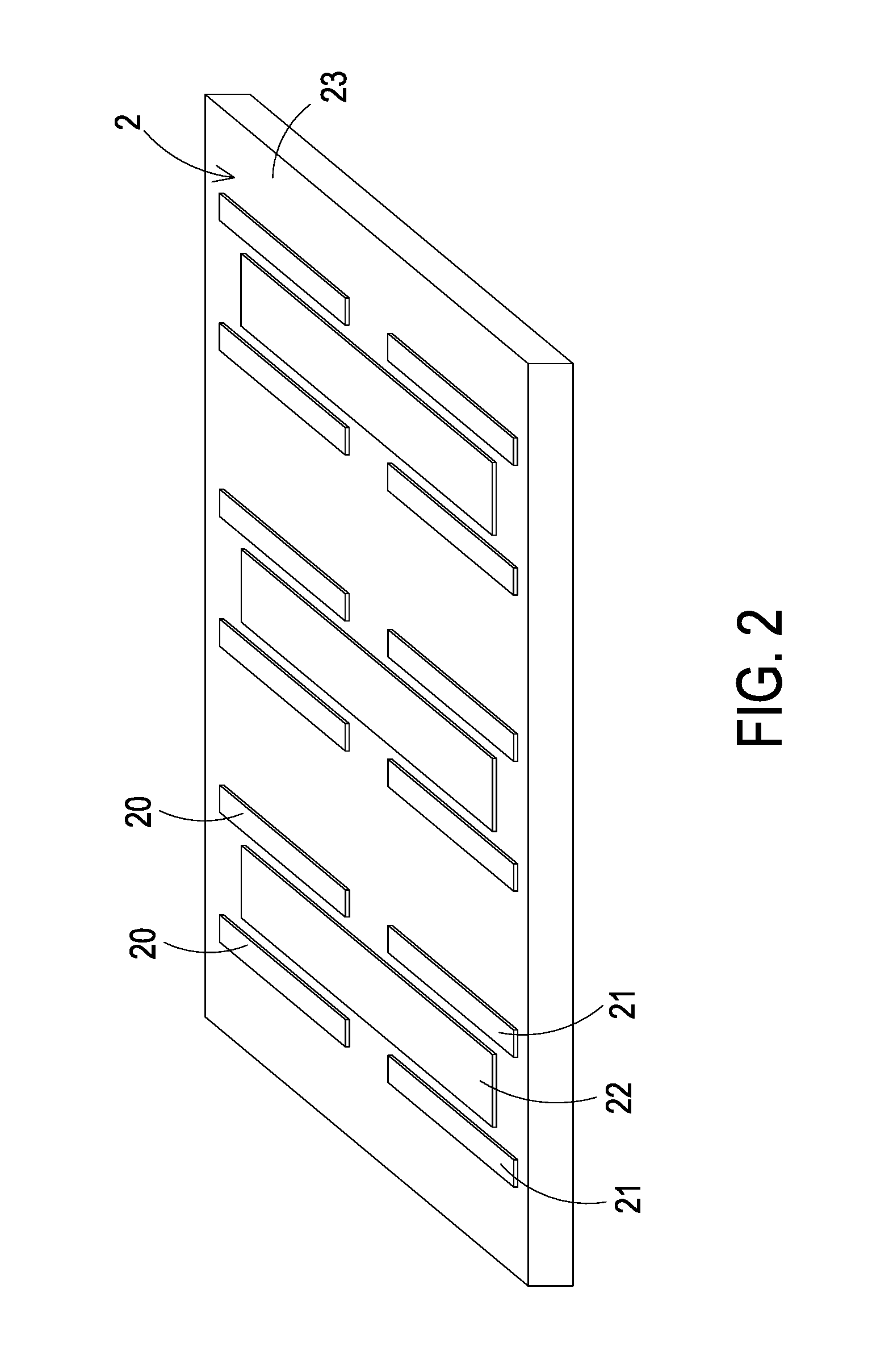
[0032]FIG. 1 is a schematic perspective view illustrating a power module according to the present invention. FIG. 2 is a schematic perspective view illustrating a substrate of the power module of FIG. 1. Please refer to FIGS. 1 and 2. The power module 1 comprises a substrate 2, at least one first sub-module 3 and at least one second sub-module 4. Moreover, plural first conducting parts 20, plural second conducting parts 21 and at least one third conducting part 22 are formed on a first surface 23 of the substrate 2.
[0033]In this embodiment, two first conducting parts 20 are located at an upper left side and an upper right side of the third conducting part 22, respectively. Moreover, two second conducting parts 21 are located at a lower left side and a lower right side of the third conducting part 22, respectively. Moreover, the first conducting parts 20, the second conducting parts 21 and the third conducting part 22 are made of electrically conductive material (e.g. copper).
[0034]T...
second embodiment
[0066]FIG. 10 is a schematic perspective view illustrating a power module according to the present invention. In comparison with the power module 1 of FIG. 1, the power module 10 of this embodiment further comprises a controlling device 100 such as a controller or a driver. The controlling device 100 is disposed on the first surface 23 of the substrate 2. Moreover, the controlling device 100, the first sub-module 3 and the at least one second sub-module 4 are located at the same side of the substrate 2. The controlling device 100 is electrically connected with the high-voltage-side switching element (i.e. the first sub-module 3) and the low-voltage-side switching element (i.e. the second sub-module 4) through electrical traces (not shown) of the substrate 2 so as to control the on / off states of the high-voltage-side switching element and the low-voltage-side switching element.
third embodiment
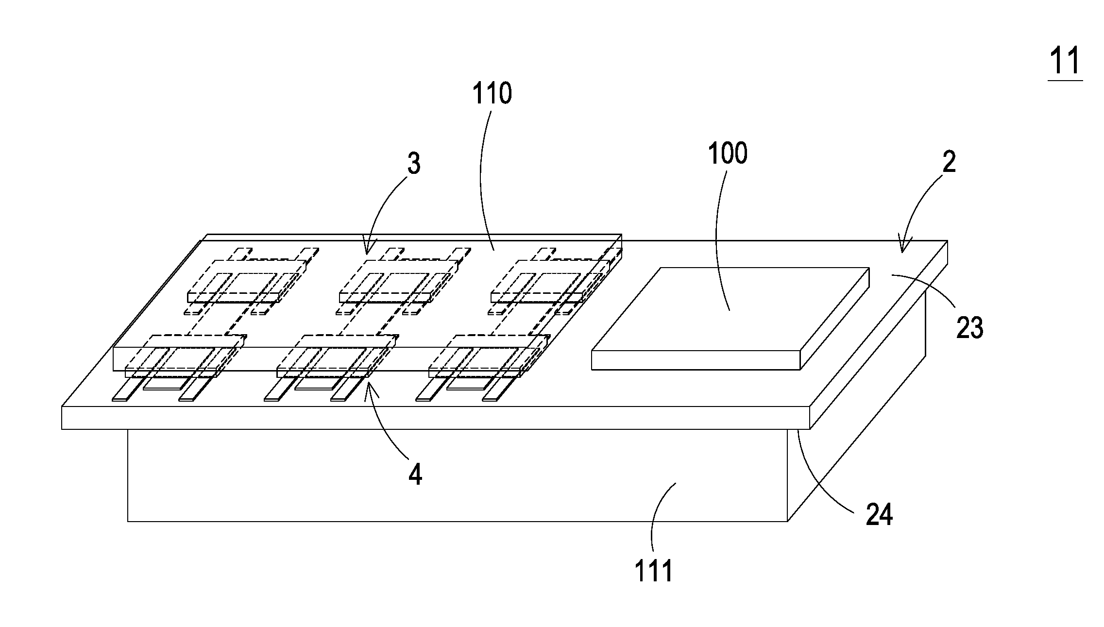
[0067]FIG. 11 is a schematic perspective view illustrating a power module according to the present invention. In comparison with the power module 10 of FIG. 10, the power module11 of this embodiment further comprises a first heat dissipation device 110 and / or a second heat dissipation device 111. The first heat dissipation device 110 is contacted with the first sub-module 3 and the second sub-module 4. That is, the first heat dissipation device 110 is contacted with the third conductive layer 36 of the first sub-module 3 and the sixth conductive layer 46 of the second sub-module 4 (see FIGS. 4 and 5). Consequently, the heat dissipating efficacy of the first sub-module 3 and the second sub-module 4 will be enhanced. The second heat dissipation device 111 is disposed on a second surface 24 of the substrate 2, which is opposed to the first surface 23 of the substrate 2. Consequently, the heat dissipating efficacy of the power module 11 will be further enhanced. Moreover, the heat gener...
PUM
 Abstract
Description
Claims
Application Information