Electronic module

Active Publication Date: 2021-02-18
SHINDENGEN ELECTRIC MFG CO LTD
View PDF0 Cites 1 Cited by
  • Summary
  • Abstract
  • Description
  • Claims
  • Application Information

AI Technical Summary

Benefits of technology

[0012]a plurality of signal terminals arranged along a first side of the substrate;
[0013]a power supply terminal, first to third motor terminals connected to coils of the three-phase motor, and a ground terminal, arranged along a second side that is opposite to the first side of the substrate;
[0014]a power supply wiring line disposed on the substrate along the first side, the power supply wiring line being connected to the power supply terminal;
[0015]a first ground wiring line disposed on the substrate alo

Problems solved by technology

Furthermore, since the shunt resistor and a signal terminal for detecting a value of the shunt resistor is away from each other (since the shunt resistor is disposed to be close to a power supply wiring line), the inductance of a path for the detected signals is great, and the inf

Method used


Image

  • Electronic module
  • Electronic module
  • Electronic module

Examples


Example

First Embodiment

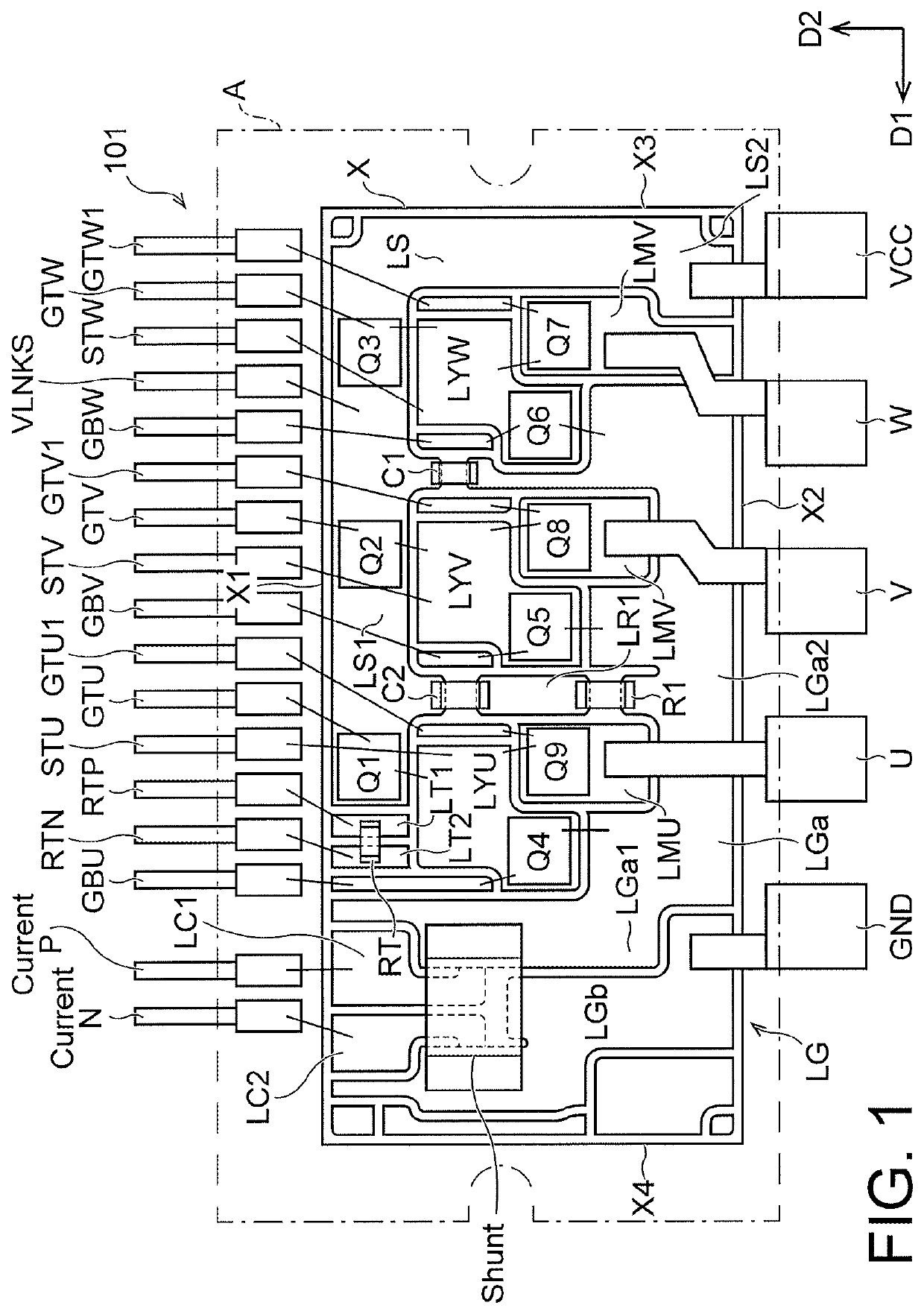
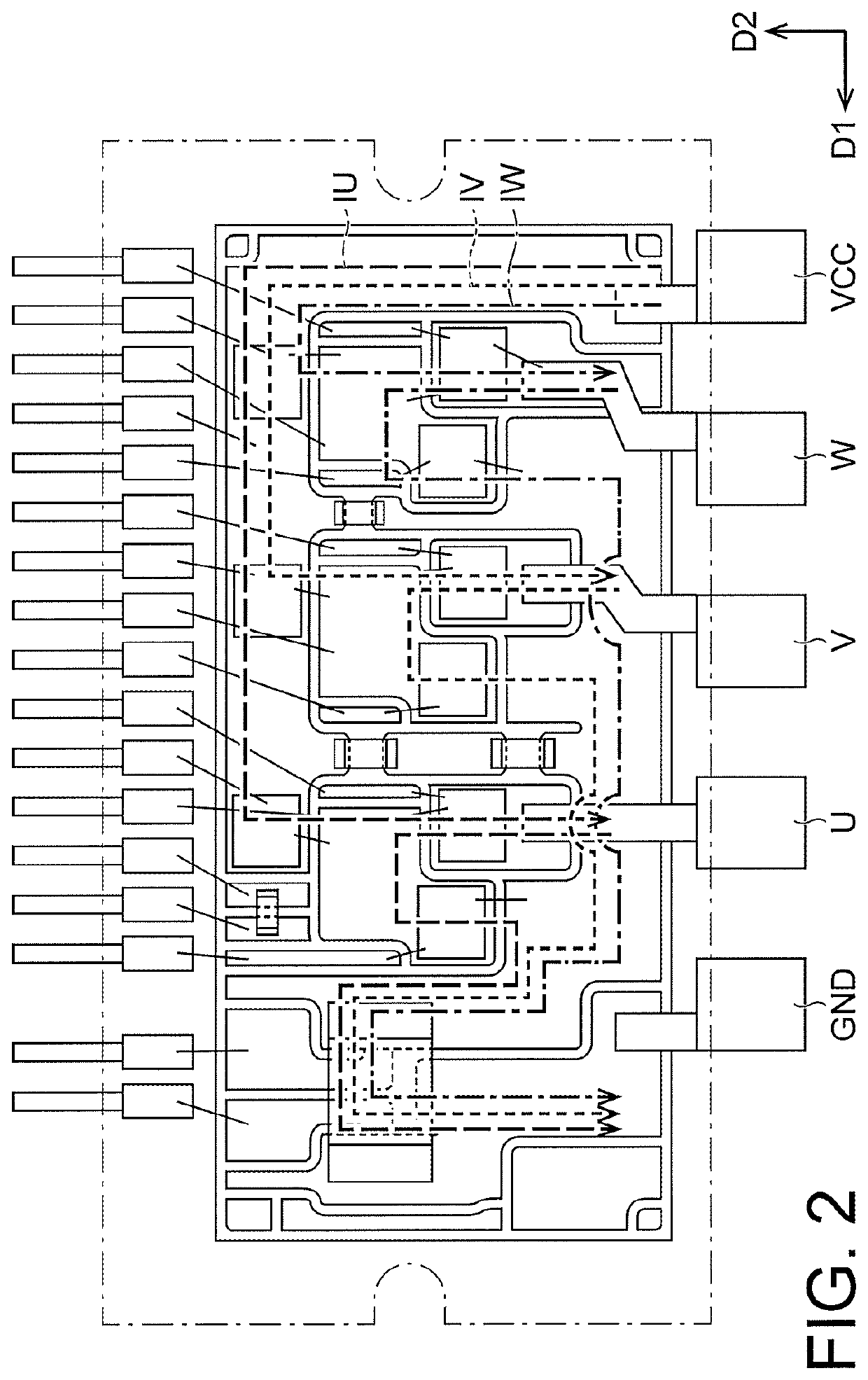
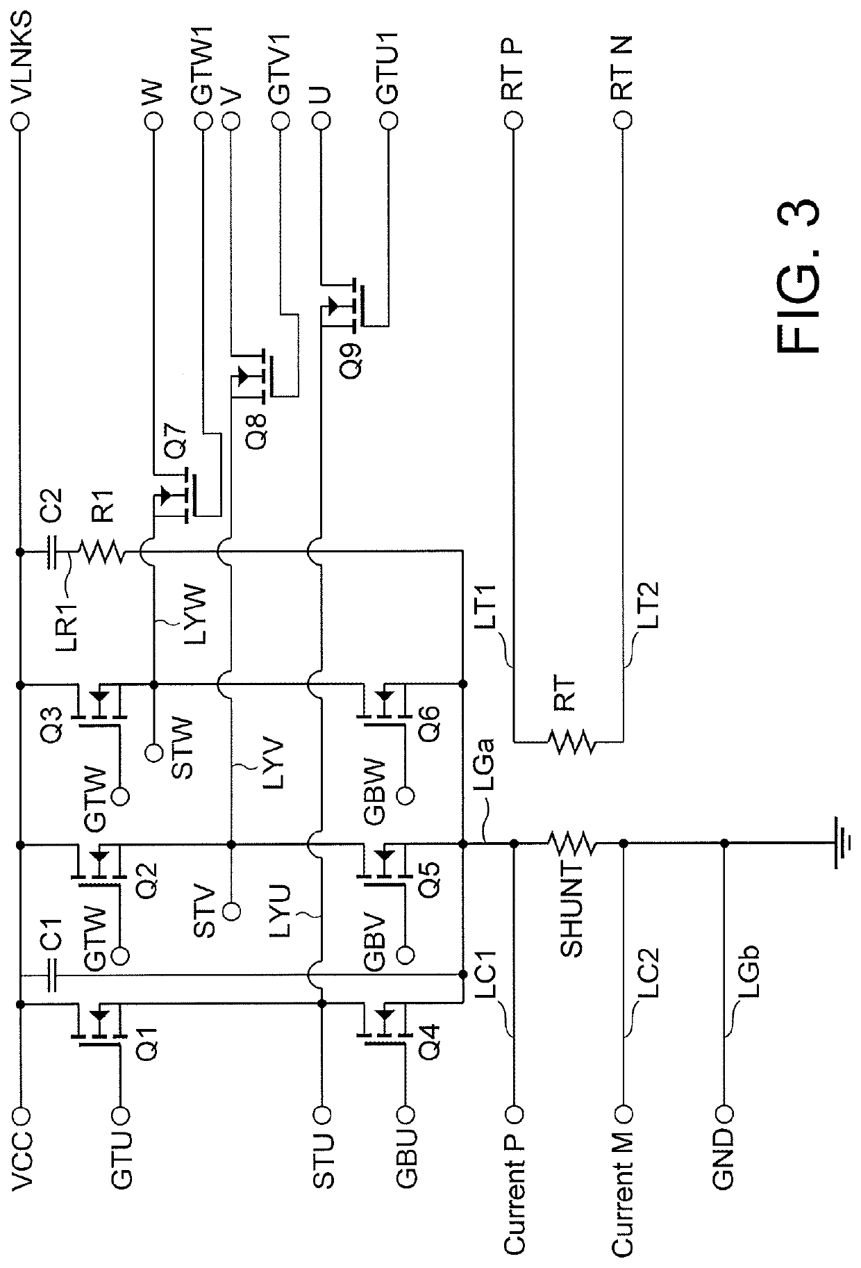
[0093]FIG. 1 is a top view of an example of a configuration of an electronic module 100 according to a first embodiment. FIG. 2 is a diagram illustrating an example of current paths of the electronic module 100 shown in FIG. 1. FIG. 3 is a circuit diagram of an example of a circuit configuration of the electronic module 100 shown in FIG. 1. In FIGS. 1 and 2, a sealing member A is illustrated to be transparent. In FIG. 2, some of the reference numerals provided in FIG. 1 are omitted for simplicity.

[0094]For example, the electronic module 100 according to the first embodiment is an inverter device configured to convert a direct current to a three-phase alternating current, and supply the three-phase alternating current to a three-phase motor to drive the three-phase motor.

[0095]As shown in FIGS. 1 to 3, the electronic module 100 includes a substrate X, a plurality of signal terminals 101, a power supply wiring line LS, a ground wiring line LG, a power supply terminal V...

Example

Second Embodiment

[0174]In the first embodiment described above, the first to third high-side switches Q1, Q2, and Q3, the first to third low-side switches Q3, Q5, and Q6, and the first to third output switches Q9, Q8, and Q7 are nMOSFET (FIG. 3). However, other types of semiconductor elements may also be used.

[0175]Specifically, the first to third high-side switches Q1, Q2, and Q3, the first to third low-side switches Q3, Q5, and Q6, and the first to third output switches Q9, Q8, and Q7 may be pMOSFETs or other semiconductor elements as long as the same function may be performed.

[0176]The configuration of the electronic module according to the second embodiment is the same as that of the first embodiment.

[0177]As described above, an electronic module according to an aspect of the present invention is an electronic module configured to convert a direct current to a three-phase alternating current, and supply the three-phase alternating current to a three-phase motor to drive the thre...


PUM


Abstract

An electronic module includes a shunt resistor having one end that is connected to one end of a first ground wiring line and another end that is connected to another end of a second ground wiring line. Signal terminals are disposed to be close to the shunt resistor, the signal terminals including a first current detection terminal electrically connected to the one end of the shunt resistor, and a second current detection terminal disposed to be close to the shunt resistor and electrically connected to the other end of the shunt resistor. The shunt resistor is disposed to be close to a first side of a substrate along which the signal terminals are arranged.

Description

TECHNICAL FIELD[0001]The present invention relates to electronic modules.BACKGROUND ART[0002]Conventionally known semiconductor devices include an electronic module configured to convert DC power inputted from a DC power supply to AC power and output the AC power.[0003]The electronic module is used, for example, to convert a DC voltage to a three-phase AC voltage for driving a three-phase motor (for example, see JP 2016-197985 A and JP 2015-020368 A).[0004]In such a conventional electronic module, a shunt resistor is provided to each phase, and a layout including power supply terminals, high-side switches, low-side switches, shunt resistors, and ground terminals is divided into respective phases, each of which has a different current path for a motor current (induced current).[0005]In other words, in the electronic module, the length of the current path for the motor current flowing through the power supply terminal, the high-side switch, the low-side switch, the shunt resistor, and...

Claims


Application Information

Patent Timeline
IPC IPC(8): H02M7/00H05K1/18H05K1/02H02P27/06H02M7/537H02K5/22H02K11/33
CPCH02M7/003H05K1/18H05K1/0228H02P27/06H02M7/537H02K5/225H02K11/27H05K2201/10166H05K2201/10022H05K2201/10196H05K2201/10015H05K2201/09227H02K11/33H02K2211/03H02K5/10H01L2224/49113H01L2924/19105H01L2224/48247
Inventor KAMIYAMA, YOSHIHIRO
Owner SHINDENGEN ELECTRIC MFG CO LTD
Why Eureka
Try Eureka