
Magnetic recording medium, the manufacturing method and magnetic recording apparatus using the same

Inactive Publication Date: 2006-12-12
WESTERN DIGITAL TECH INC +1
View PDF3 Cites 11 Cited by
  • Summary
  • Abstract
  • Description
  • Claims
  • Application Information

AI Technical Summary

Benefits of technology

[0012]The present invention has been made in view of the above circumstances and provides a magnetic recording medium which is increased in the chemi

Problems solved by technology

However, the DLC protective layers obtained by these methods cannot achieve satisfactory slide resistance when the thickness of the layer is smaller than 4 nm.
When the floating height of a magnetic head is reduced to around 10 nm, contact between the magnetic head and a magnetic recording medium occurs intermittently, whereby floating is not stabilized with the result that writing and reading become impossible.
Therefore, the problem is that the bonding strength to perfluoropolyether lubricant applied to the protective layer is weak owing to fewer functional groups.
When the rotating speed of the magnetic recording medium is increased, however, centrifugal force is applied to the liquid lubricant on the DLC protective layer of the magnetic recording medium so that as the result of the problem that the bonding strength is weak, the liquid lubricant is d

Method used


Image

  • Magnetic recording medium, the manufacturing method and magnetic recording apparatus using the same
  • Magnetic recording medium, the manufacturing method and magnetic recording apparatus using the same
  • Magnetic recording medium, the manufacturing method and magnetic recording apparatus using the same

Examples


Example

COMPARATIVE EXAMPLE 2

[0159]Sample No. 4 was prepared in the same manner as sample No. 3 in Embodiment 4 except that a nitrous oxide gas was not supplied to form a DLC protective layer 37 and the flow rate of the ethylene gas was fixed at 30 sccm. The thickness of the DLC protective layer 37 was 3.5 nm. This sample was evaluated in the same manner as sample No. 3 and the obtained results are shown in FIGS. 10, 11 and 12.

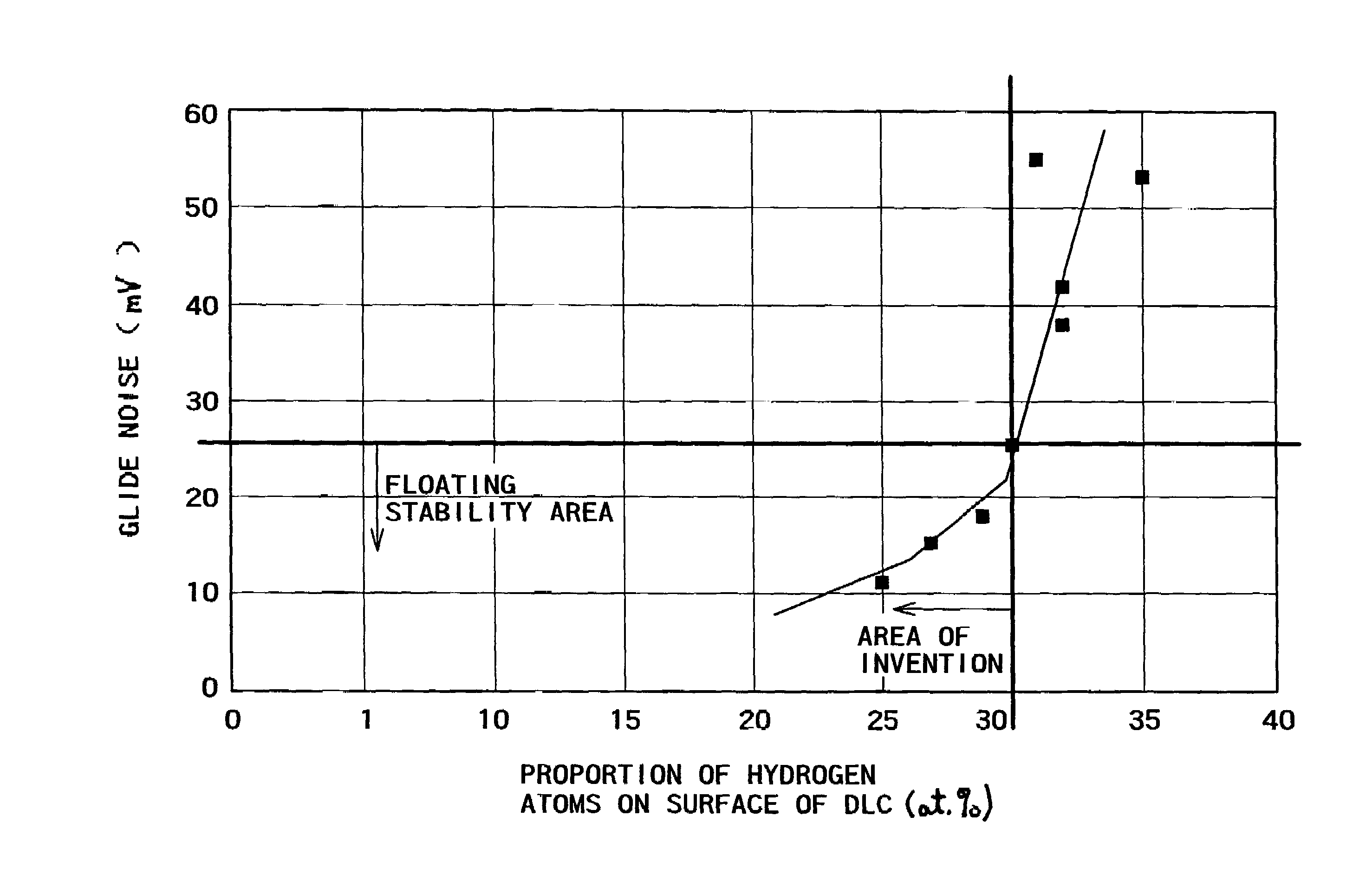
[0160]As a result, the proportion of hydrogen atoms on the surface of DLC was 35%, the proportion of hydrogen atoms in the interior of DLC was 37%, and the proportion of nitrogen atoms contained in the DLC protective layer was below the detection limit.

[0161]The thickness of the lubricant layer 38 was 1.1 nm which was smaller than that of sample No. 3, and the thickness of the fixed layer of the lubricant chemically bonded was very small at 0.4 nm.

[0162]Glide noise when the flyability of the magnetic head were evaluated was extremely large at 53 mV as an average value...

Example

COMPARATIVE EXAMPLE 3

[0165]Sample No. 5 was prepared in the same manner as sample No. 3 of Embodiment 4 except that the flow rate of an ethylene gas was fixed at 30 sccm to form a DLC protective layer 37. The thickness of the DLC protective layer 37 was 3.5 nm. This sample was evaluated in the same manner as sample No. 3, and the obtained results are shown in FIGS. 10, 11 and 12.

[0166]As a result, the proportion of hydrogen atoms on the surface of DLC was 31%, the proportion of hydrogen atoms in the interior of DLC was 36%, and the proportion of nitrogen atoms contained in the DLC protective layer was 4.1%.

[0167]The thickness of the lubricant layer 38 was 1.6 nm which was almost the same as sample No. 3, and the thickness of the fixed layer of the lubricant chemically bonded was 1.0 nm which was almost the same as sample No. 3.

[0168]Glide noise when the flyability of the magnetic head were evaluated was very large at 55 mV as an average value of three magnetic disks. Thus, it was fo...

Example

COMPARATIVE EXAMPLE 4

[0171]Sample No. 6 was prepared in the same manner as sample No. 3 of Embodiment 4 except that the nitrous oxide gas was not added to form the DLC protective layer 37. The thickness of the DLC protective layer 37 was 3.5 nm. This sample was evaluated in the same manner as sample No. 3, and the obtained results are shown in FIGS. 10, 11 and 12.

[0172]As a result, the proportion of hydrogen atoms on the surface of DLC was 32%, the proportion of hydrogen atoms in the interior of DLC was 36%, and the proportion of nitrogen atoms contained in the DLC protective layer was below the detection limit.

[0173]The thickness of the lubricant layer 38 was 1.0 nm which was smaller than sample No. 3, and the thickness of the fixed layer of the lubricant chemically bonded was extremely small at 0.4 nm.

[0174]Glide noise when the flyability of the magnetic head were evaluated was very large at 42 mV as an average value of three magnetic disks. Thus, it was found that the magnetic di...


PUM


Abstract

This magnetic recording medium is characterized in that in the magnetic recording medium having a magnetic layer on a non-magnetic substrate by intercalating at least an under layer, the proportion of functional groups per 100 carbon atoms in a diamond-like carbon protective layer mainly composed of carbon for protecting the magnetic layer exceeds 20%. The bonding force between the protective layer and the lubricating layer of the magnetic recording medium is increased so that under high speed rotation, a decrease in the lubricating layer is not caused so as to provide a magnetic recording apparatus having high reliability.

Description

[0001]This is a Continuation-In-Part application of Ser. No. 09 / 784,952 filed Feb. 16, 2001, the disclosure of which is hereby incorporated by reference.BACKGROUND OF THE INVENTION[0002]This invention relates to a magnetic recording medium which has excellent reliability and in which magnetic recording is performed with high density, a manufacturing method thereof and a magnetic disc device used in an auxiliary storage apparatus of a computer.[0003]A magnetic disc apparatus used in a storage apparatus of a large-scale computer, a work station, a personal computer and the like has been yearly increased in its importance and developed into a mass-stored and small sized device. Increasing of recording density is essential to the development of the magnetic disc apparatus into mass-stored and small-sized apparatus. As the technology for realizing the development into the mass-stored and small-sized device, cited is reduction in distance between a magnetic recording layer of a magnetic r...

Claims


Application Information

Patent Timeline
IPC IPC(8): G11B5/66G11B5/70G11B5/72G11B5/84
CPCG11B5/72G11B5/8408G11B5/7266
Inventor ONO, TOSHINORIKOKAKU, YUUICHIMATSUMOTO, HIROYUKITANI, HIROSHISHODA, MITSUHIROKOZAKI, TOMONORIISHIKAWA, HIROSHIYATSUE, TORUHONDA, YOSHINORIFUJIMAKI, SHIGEHIKO
Owner WESTERN DIGITAL TECH INC
Learn More