
Charge transfer capacitive position sensor

a capacitive position sensor and charge transfer technology, applied in the field of human interface apparatus and methods, can solve the problems of inability to inability to easily meet the demand for capacitive material displacement sensors, and inability to easily meet the current generation of non-mechanical transducers, etc., to achieve the effect of small siz

Inactive Publication Date: 2006-12-12
ATMEL CORP
View PDF22 Cites 182 Cited by
  • Summary
  • Abstract
  • Description
  • Claims
  • Application Information

AI Technical Summary

Benefits of technology

[0023]In a modification of this second embodiment, the discrete conductive electrodes are of sufficiently small size and the insulating substrate is thick enough to permit field blending, which effectively “smoothes” the sensed position of the pointing object on the sensing side of the substrate.
[0026]It is an additional object of some embodiments of the invention to provide a one-dimensional reading of an amount of material displacement, e.g. fluid level or piston extension, along the strip. This increases the distributed capacitance along the strip as more of the strip is covered.

Problems solved by technology

Similarly, there is a significant demand for capacitive material displacement sensors (e.g. fluid level sensors, mechanical movement sensors, pressure sensors etc.) at lower price points, which cannot be easily met with current generations of non-mechanical transducers.
Many such applications are incompatible with the expense, reduced contrast, and fragility of touch screens.
Moreover, the performance of some of these suffer from deep or limited menu options and visual parallax.
Electromechanical human interface controls (such as pushbuttons, membrane switches, and potentiometers) have the noted defects of being unreliable and subject to water ingress, as well as being only marginally compatible with LCD-based menu systems.
They also do not present a ‘clean’ appearance, are considered increasingly quaint, and seriously limit the flexibility of industrial designers.
This solution still requires a knob, is expensive to manufacture, and only works well as a rotary device, although many applications require linear sensing.
Such devices are usually high-cost solutions, albeit very accurate, and rely on magnetic field balance measurements made with expensive signal conditioners.
RCDT capacitive transducer, which also requires a special, expensive signal conditioner to operate.
The above referenced technologies however suffer the problem of being very complex and expensive to manufacture, limiting their use to high-end or industrial equipment.
LVDT and RCDT type transducers work very well, but leave untapped a very large market for low cost devices which can be used commercially in automotive and appliance applications.
Existing capacitive fluid sensors are not very popular due to their cost or inability to compensate automatically for changes in dielectric properties.
Few are capable of accurately sensing fluid level from outside a plastic or glass vessel.

Method used


Image

  • Charge transfer capacitive position sensor
  • Charge transfer capacitive position sensor
  • Charge transfer capacitive position sensor

Examples


Embodiment Construction

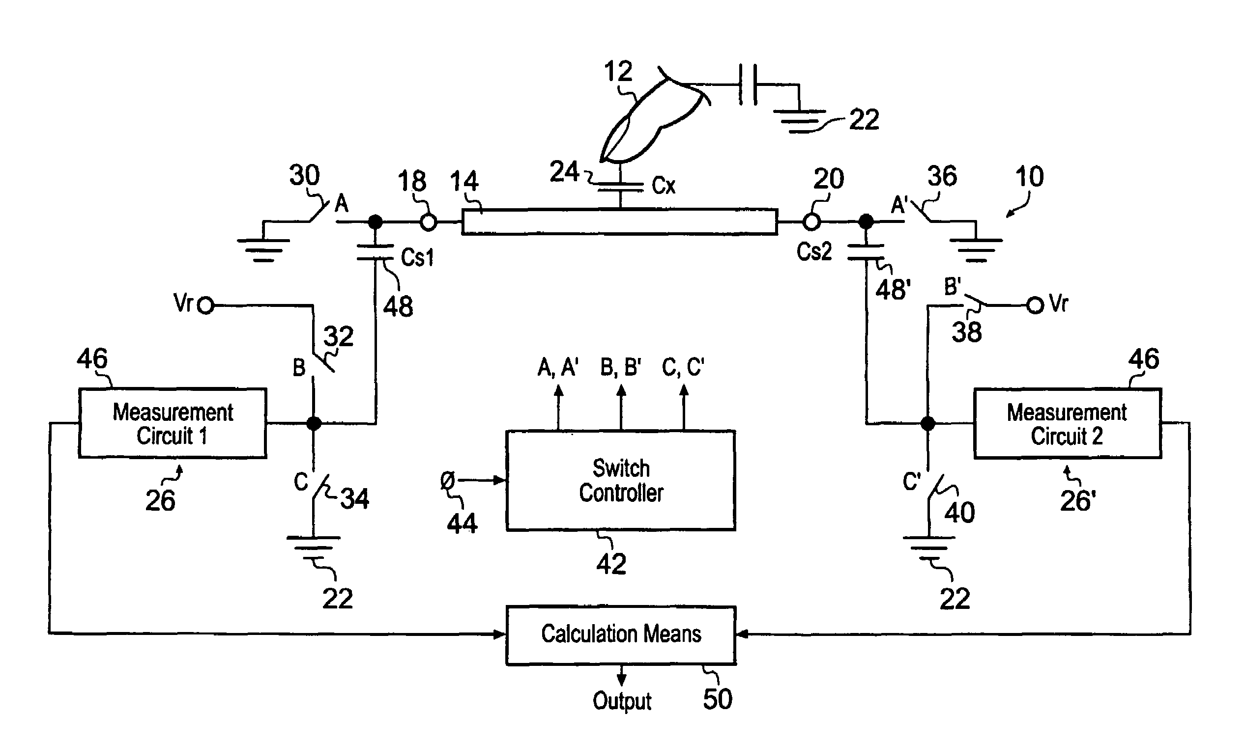
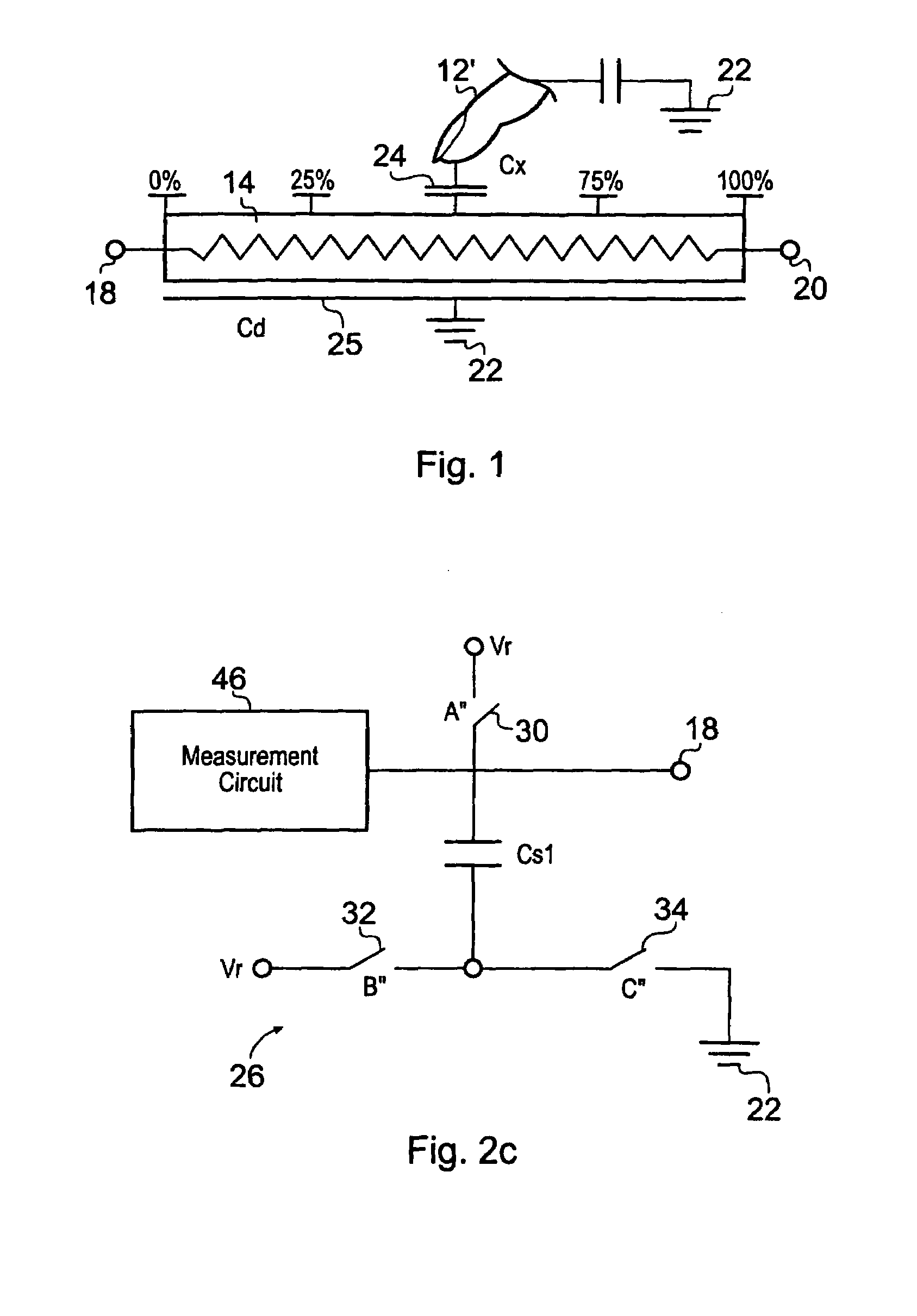
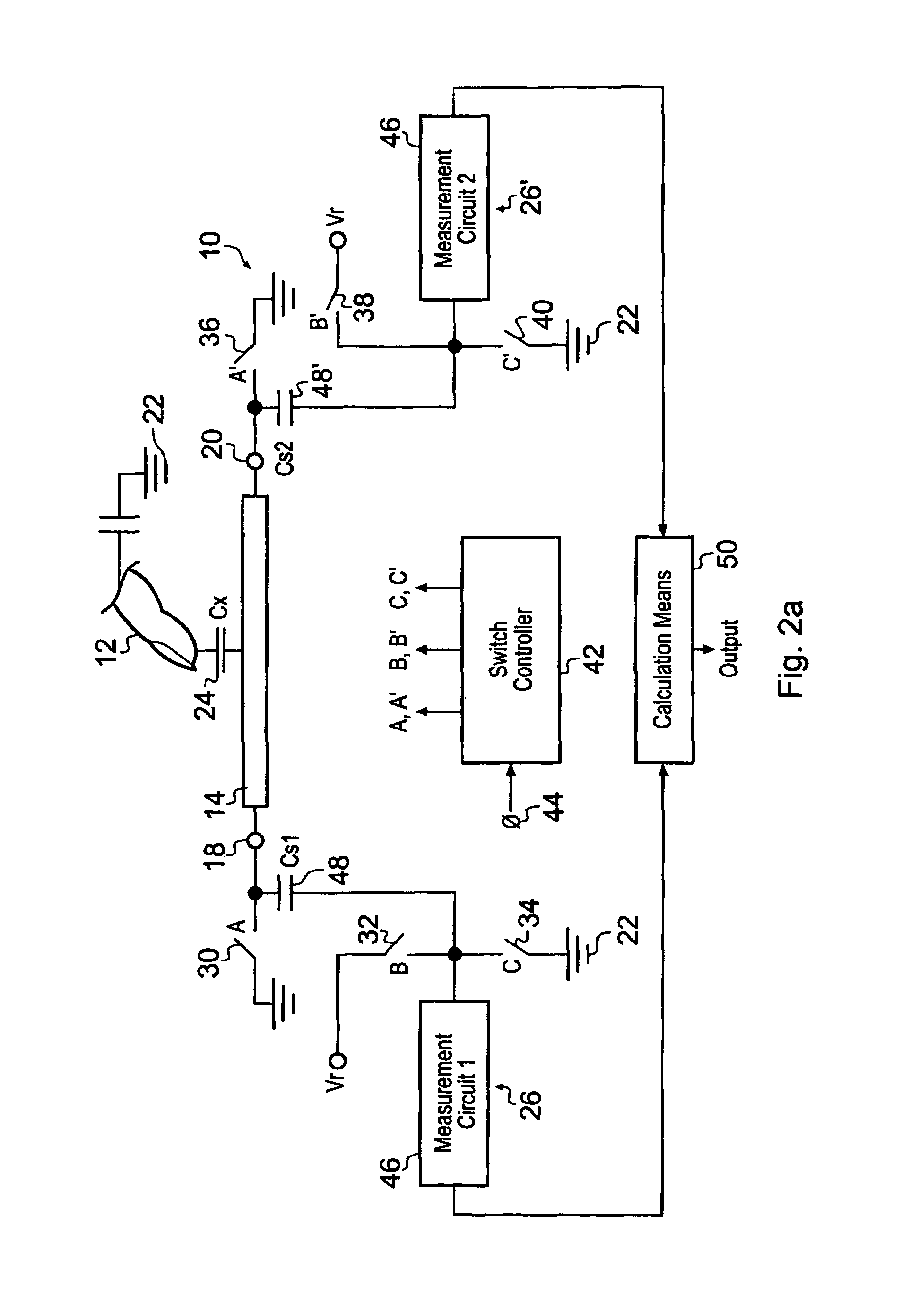
[0048]In studying this Detailed Description, the reader may be aided by noting definitions of certain words and phrases used throughout this patent document. Wherever those definitions are provided, those of ordinary skill in the art should understand that in many, if not most instances, such definitions apply to prior, as well as future uses of such defined words and phrases. At the outset of this Description, one may note that the terms “include” and “comprise,” as well as derivatives thereof, mean inclusion without limitation; the term “or,” is inclusive, meaning and / or; “resistive body” may stand for a sensing strip used in a capacitive mode and made of a galvanically conductive substance; the words “finger” or “sensed object” stand for an actual human finger, any other bodily appendage or for any mechanical object capable of being sensed proximate the element; the word “touch” stands for physical proximity or for contact by a finger to the element of the invention even if there...


PUM


Abstract

The position of an object, which may be a user's finger, along a body is sensed capacitively. A measurement circuit meters the simultaneous injection of electrical charge into the two ends of the body, which may be shaped as a straight line or as a curve. A computing device computes the ratio of the relative changes in the amount of charge injected into each end of the element. The result of this computation is a one dimensional coordinate number plus a detection state indication, both of which can be fed to another functional element, such as an appliance controller, which interprets the coordinate and detection state as a command or measurement.

Description

CROSS REFERENCE TO OTHER APPLICATIONS[0001]This application claims the priority of the inventor's U.S. Provisional Application for Patent filed on Oct. 31, 2002 and having Ser. No. 60 / 422,837.FIELD OF THE INVENTION[0002]The invention provides apparatus and methods for human interfaces to electronic apparatus as well as for sensing material displacement. More particularly, the invention pertains to capacitive sensing of a position along a line or curve.BACKGROUND INFORMATION[0003]Capacitive sensors have become increasingly common and accepted for use in human interfaces and for machine control. In the field of home appliances it is now quite common to find capacitive touch controls operable through glass or plastic panels. These sensors are increasingly typified by my U.S. Pat. No. 6,452,514, the disclosure of which is herein incorporated by reference, which describes a matrix sensor approach employing charge-transfer principles.[0004]Due to increasing market demand for capacitive to...

Claims


Application Information

Patent Timeline
Patent Type & Authority Patents(United States)
IPC IPC(8): G01R27/26G01M19/00G01D5/24G01D5/241G01M99/00G06F3/033G06F3/044
CPCG01D5/24G06F3/044G01D5/2412G06F3/0443G06F3/03
Inventor PHILIPP, HARALD
Owner ATMEL CORP
Learn More