Bendable display apparatus and method of manufacturing the same

Inactive Publication Date: 2006-12-12
JAPAN DISPLAY CENT INC
View PDF33 Cites 35 Cited by
  • Summary
  • Abstract
  • Description
  • Claims
  • Application Information

AI Technical Summary

Benefits of technology

[0010]The present invention has been made in order to solve the above problems, and its object is to provide a display apparatus and a manufacturing method thereof, which can achieve further reduction in thickness while m

Problems solved by technology

However, fabrication with use of a glass substrate that has a thickness of less than 0.5 mm may lead to a decrease in manufacturing yield, since conveyance, etc. thereof is difficult because of a problem of bending due to its own weight.
A display apparatus formed with such a substrate may easily suffer crack or chip at its end part due to weak shock, and moreover the entirety of the apparatus may be broken.
This, howev

Method used


Image

  • Bendable display apparatus and method of manufacturing the same
  • Bendable display apparatus and method of manufacturing the same
  • Bendable display apparatus and method of manufacturing the same

Examples


first embodiment

(First Embodiment)

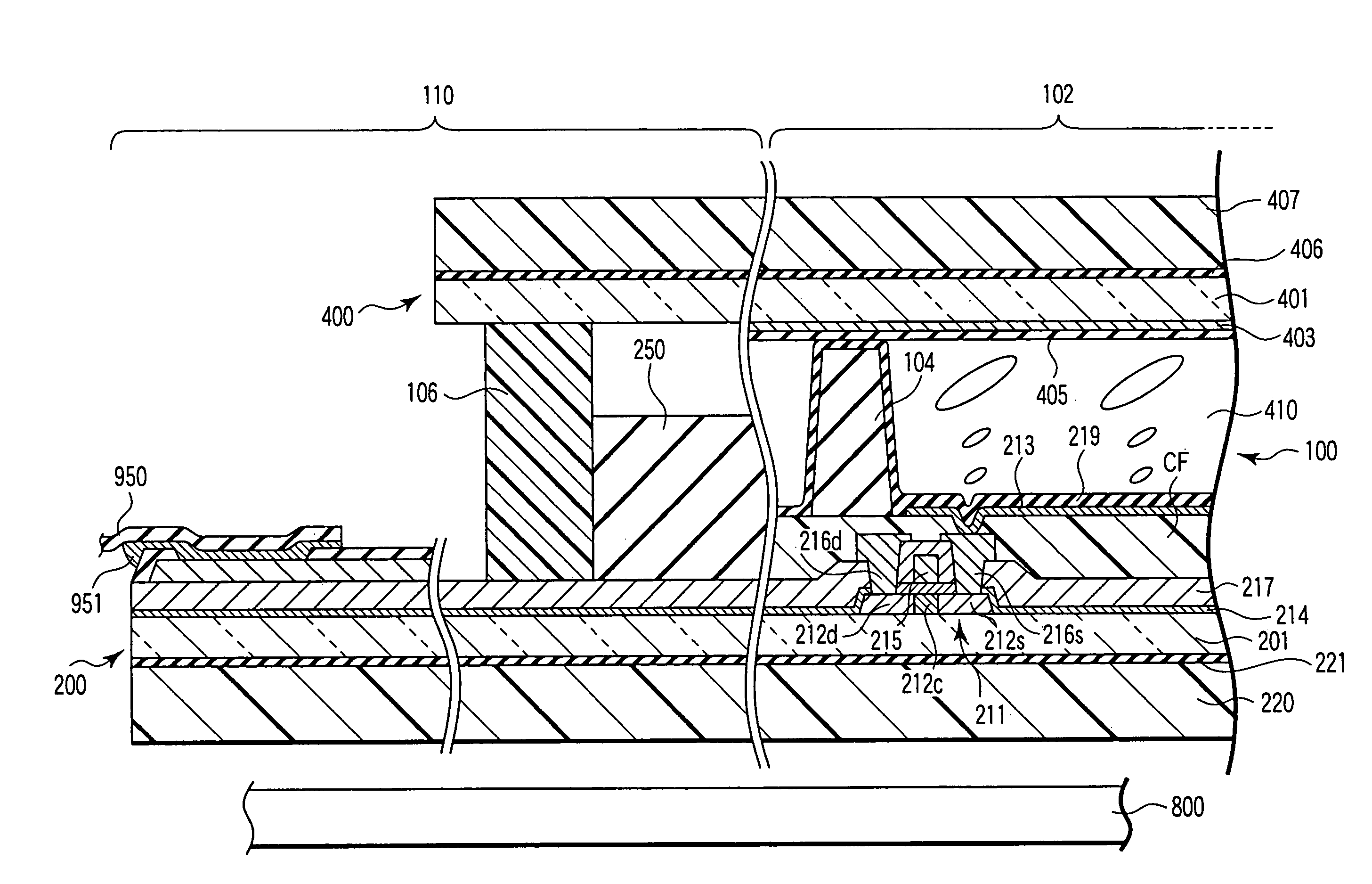
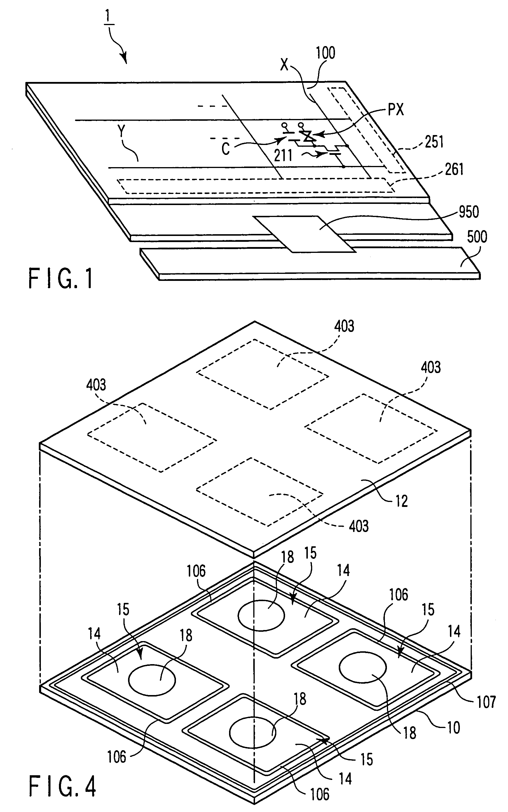
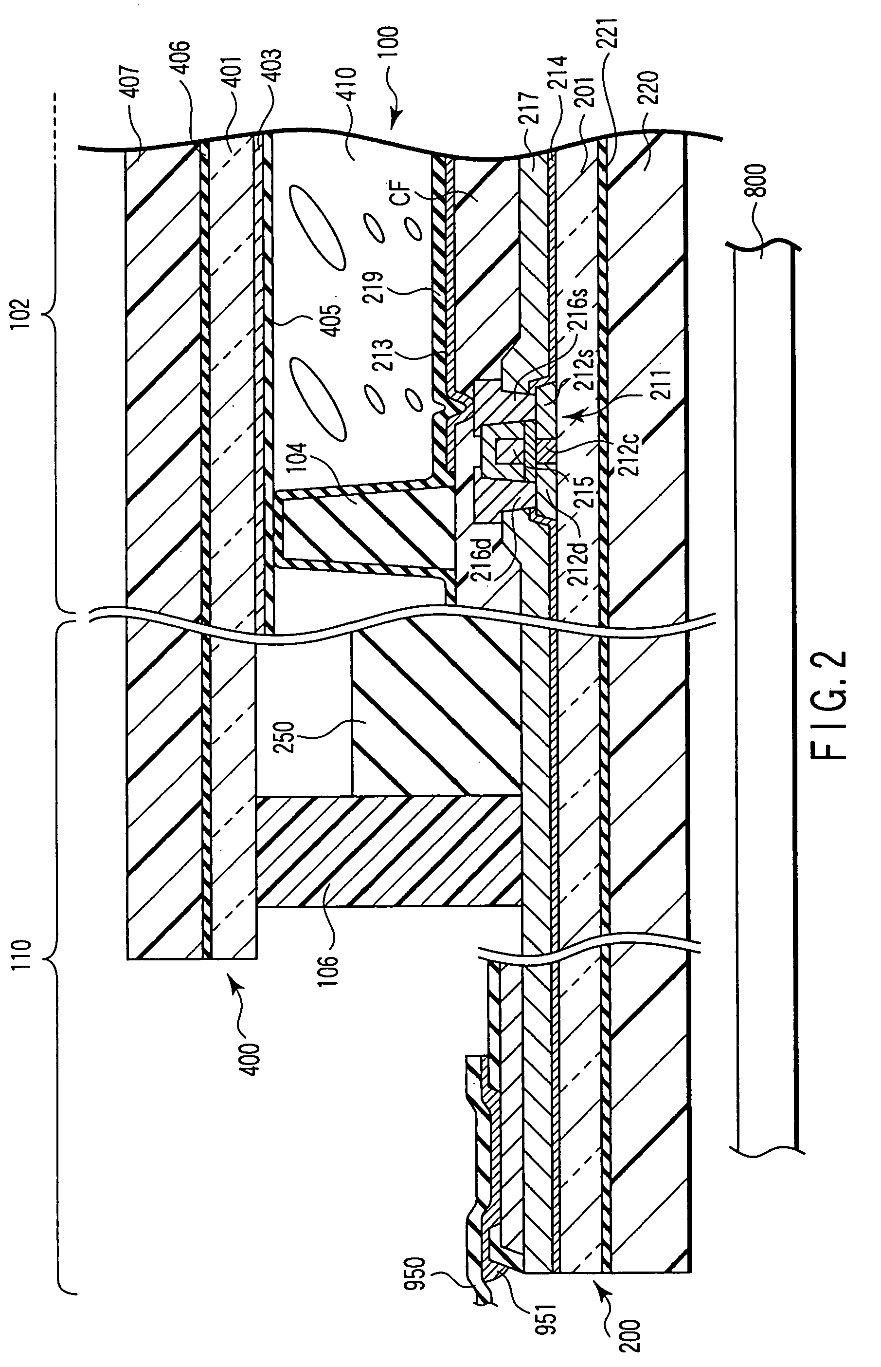
[0043]As is shown in FIG. 1 and FIG. 2, a display apparatus according to a first embodiment, that is, a liquid crystal display apparatus 1, comprises a light-transmission type liquid crystal panel 100, a drive circuit board 500 that supplies drive signals to the liquid crystal panel 100, and a backlight unit 800 that illuminates the liquid crystal panel 100 from its back side. The liquid crystal panel 100 and drive circuit board 500 are electrically connected by a flexible wiring board 950. The flexible wiring board 950 is electrically connected to the liquid crystal panel 100 and drive circuit board 500 by, e.g. an anisotropic conductive film (ACF) 951.

[0044]The liquid crystal panel 100 has an effective display region 102 with a diagonal size of 12.1 inches. The effective display region 102 includes a plurality of display pixel sections PX arranged in a matrix. The liquid crystal panel 100 includes an array substrate 200, a counter substrate 400, and a liquid crys...

second embodiment

(Second Embodiment)

[0091]As is shown in FIG. 1 and FIG. 3, a display apparatus according to a second embodiment, that is, a liquid crystal display apparatus 1, comprises a reflection type liquid crystal panel 100, and a drive circuit board 500 that supplies drive signals to the liquid crystal panel 100. Depending on cases, a planar light source section serving as a front light may be disposed on the display surface side of the reflection type liquid crystal panel 100. The structural elements common to those in the above-described first embodiment are denoted by like reference numerals, and a detailed description thereof is omitted.

[0092]The array substrate 200 and counter substrate 400 include light-transmissive insulation substrates 201 and 401, each of which is formed of glass with a thickness of 0.15 mm or less, preferably 0.1 mm or less (with a thickness of 0.1 mm in the second embodiment).

[0093]The pixel electrode 213 is formed of a light-reflective conductive material such as ...

third embodiment

(Third Embodiment)

[0111]As is shown in FIG. 1 and FIG. 9, a display apparatus according to a third embodiment, that is, a liquid crystal display apparatus 1, comprises a light-transmission type liquid crystal panel 100, a drive circuit board 500 that supplies drive signals to the liquid crystal panel 100, a backlight unit 800 that illuminates the liquid crystal panel 100 from its back side, and a touch panel 1100. The liquid crystal panel 100 and drive circuit board 500 are electrically connected by a flexible wiring board 950. The flexible wiring board 950 is electrically connected to the liquid crystal panel 100 and drive circuit board 500 by, e.g. an anisotropic conductive film (ACF) 951.

[0112]As is shown in FIG. 11, the touch panel 1100 generates an input signal by sensing a contact position within a predetermined region 1101. The touch panel 1100 comprises a conductor layer 1103 that is disposed in the predetermined region 1101, detection electrodes 1105A, 1105B, 1107A and 1107...


PUM


Abstract

A display apparatus with a plurality of display pixel sections includes glass substrate, which are formed to have a thickness that permits bending of the display apparatus, and polarizer plates, which are disposed on the glass substrates, respectively. The polarizer plates are thicker than the glass substrates.

Description

CROSS-REFERENCE TO RELATED APPLICATIONS[0001]This is a Continuation Application of PCT Application No. PCT / JP03 / 06071, filed May 15, 2003, which was not published under PCT Article 21 (2) in English.[0002]This application is based upon and claims the benefit of priority from prior Japanese Patent Applications No. 2002-143812, filed May 17, 2002; No. 2002-143813, filed May 17, 2002; No. 2002-143814, filed May 17, 2002; and No. 2003-134349, filed May 13, 2003, the entire contents of all of which are incorporated herein by reference.BACKGROUND OF THE INVENTION[0003]1. Field of the Invention[0004]The present invention relates to a display apparatus and a manufacturing method thereof, and, more particularly, to a structure of a display apparatus that can achieve reduction in thickness.[0005]2. Description of the Related Art[0006]Flat panel display apparatuses represented by a liquid crystal display apparatus are applied to various fields, taking advantage of such features as light weight...

Claims


Application Information

Patent Timeline
IPC IPC(8): G02F1/1333G02F1/1335G02F1/13357G02F1/1339G02F1/1368G06F3/041G09F9/30H01L27/32H01L51/50H01L51/52H05B33/02H05B33/10
CPCG02F1/133305G02F1/133528G02F1/13394H01L51/5237H01L51/5281G02F2001/13356H01L2251/558H01L2251/5338H01L27/3244G02F1/13356H10K59/12H10K50/841H10K50/86H10K2102/351H10K2102/311G02F1/1335
Inventor KINOSHITA, MASAKIKAWAMATA, KENJIYAMANAKA, SATORUKURISU, HIROYUKIMIYAZAKI, TATSUYAKAWATA, YASUSHI
Owner JAPAN DISPLAY CENT INC
Why Eureka
Try Eureka