Apparatus and methods for modifying a model of an object to enforce compliance with a manufacturing constraint

a technology of modifying a model and an object, applied in the field of computer-aided design of manufactured objects, can solve the problems of difficult to change the model of an object, improperly designed objects may get stuck in the mold, and insufficient extraction, so as to enhance the interactivity of the design process and facilitate processing

Active Publication Date: 2006-12-12
3D SYST INC
View PDF208 Cites 62 Cited by
  • Summary
  • Abstract
  • Description
  • Claims
  • Application Information

AI Technical Summary

Benefits of technology

[0012]The invention provides a method of automatically modifying a three-dimensional model, regardless of its shape, at any stage of the design process. As a result, the designer is free to explore shape and form without the burden of anticipating manufacturing constraints during the early design stages.
[0013]Methods of the invention extend the flexibility of CAD systems by automatically adapting CAD models for compatibility with manufacturing processes. Methods of the invention provide high commercial value to designers of moldable objects and / or products in various markets, including toys, collectibles, athletic wear, and electronic devices, for example. The cost of designing products can be reduced, and manufacturing flexibility enhanced by using these methods.
[0018]The invention provides methods that work with an arbitrarily-shaped three-dimensional model, regardless of the sequence of steps that were used to generate the model. Both the model and the parting curve can have arbitrary shape. Thus, it is not necessary to use particular types of primitives to represent a given shape in the model. This provides an advantage, since many primitives cannot be modified to add draft angle at all, while others require careful advance planning to support draft angle modifications. The flexibility of voxels to represent and modify any arbitrary 3D shape allows methods of the invention to operate on arbitrarily-shaped 3D models.
[0022]The use of voxel representation is compatible with and complementary to the haptic rendering of the model. In one embodiment, the method further includes the step of graphically and / or haptically rendering the model, for example, following the automatic modification according to the manufacturing constraint. For example, an embodiment of the invention includes haptically rendering the model of the object as a user edits the model. Haptic rendering allows a user to “feel” the object as he modifies it, enhancing the interactivity of the design process. The haptic rendering process includes determining a force feedback corresponding to a position of a haptic interface device held by the user as the user edits the model. The force is delivered to the user via the haptic interface device. A haptic rendering process is described, for example, in co-owned U.S. Pat. No. 6,552,722, by Shih et al., and co-owned U.S. Pat. No. 6,421,048, by Shih et al., both of which are incorporated herein by reference in their entirety. The haptic interface device may be, for example, the Phantom® haptic interface device manufactured by SensAble Technologies, Inc., of Woburn, Mass., as described in U.S. Pat. No. 6,417,638, issued to Rodomista et al., the entirety of which is incorporated herein by reference. Other descriptions of haptic rendering processes and haptic interface devices include co-owned U.S. Pat. No. 6,084,587, by Aviles et al., and co-owned U.S. Pat. No. 6,191,796, by Tarr, both of which are incorporated herein by reference in their entirety. For example, the haptic interface device is a six degree of freedom force-reflecting tool that includes three powered axes and three free axes, all of which are tracked so that the position of a user connection element in the virtual environment of the model can be determined and a corresponding force applied. The haptic interface device, therefore, can double as a graphical interface device.
[0023]In one embodiment, the array of voxel values includes one-byte integers. Furthermore, the array may consist entirely or essentially of one-byte integers. Use of one-byte integers allows for fast processing, which is particularly important where the model is haptically rendered and / or where the number of voxels in the voxel volume is large. Of course, it is not necessary that the voxel values be integers. For example, the voxel values may be floating point values of any precision.
[0033]In one embodiment, the processor is adapted to provide a haptic / graphical user interface element (“widget”). The widget enables a user to interactively and intuitively select aspects of a manufacturing constraint and to provide a signal for the automatic modification of the model to begin. In one embodiment, the widget allows a user to specify one or more of a draft angle, a parting curve, and a parting direction. The processor is preferably adapted to provide a graphical representation of the position, scale, and / or orientation of the widget in relation to the model. The processor may also be adapted to provide a haptic representation of the widget, including, for example, hotspots, detents, gravity wells, and / or other haptic cues to facilitate manipulation by the user.

Problems solved by technology

An improperly designed object may get stuck in the mold and not extract properly.
It is often difficult to change a model of an object to enforce a manufacturing constraint in the late stages of design.
For example, it is often difficult to modify a boundary representation (BREP) model of an object to correct for inadequate draft.
The difficulty lies with topology limitations of such models.
If a BREP model needs to be modified in the late stages of design, only a very limited set of simple shape modifications may be made.
Satisfactory modification of the model may be impossible if the model was not constructed carefully, for example, by using “draft-friendly” primitives (elementary geometric elements) in troublesome regions.
Moreover, use of draft-friendly primitives may be aesthetically unsatisfactory or otherwise unacceptable for certain applications.
Furthermore, changing a design to comply with a manufacturing constraint generally requires expert knowledge about the manufacturing process—knowledge that the designer may not possess.
Modification may be made early in the design stage, where the burden is imposed on the designer to anticipate likely manufacturing problems, or during the manufacturing stage, where the cost of changing the design may be prohibitive.

Method used


Image

  • Apparatus and methods for modifying a model of an object to enforce compliance with a manufacturing constraint
  • Apparatus and methods for modifying a model of an object to enforce compliance with a manufacturing constraint
  • Apparatus and methods for modifying a model of an object to enforce compliance with a manufacturing constraint

Examples


Embodiment Construction

[0065]Throughout the description, where an apparatus is described as having, including, or comprising specific components, or where systems, processes, and methods are described as having, including, or comprising specific steps, it is contemplated that, additionally, there are apparati of the present invention that consist essentially of, or consist of, the recited components, and that there are systems, processes, and methods of the present invention that consist essentially of, or consist of, the recited steps.

[0066]It should be understood that the order of steps or order for performing certain actions is immaterial so long as the invention remains operable. Moreover, two or more steps or actions may be conducted simultaneously.

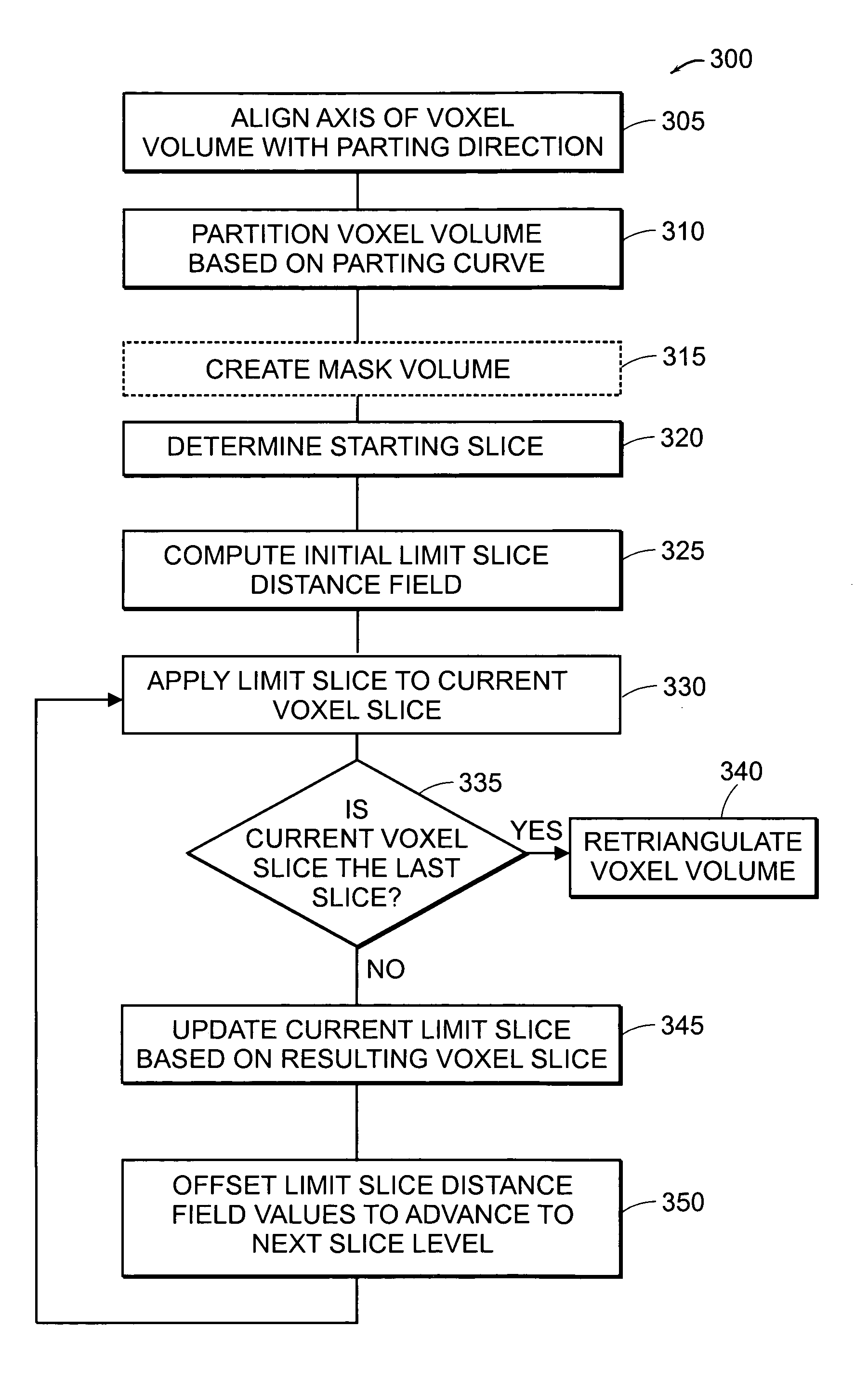
[0067]It is an object of the invention to leverage the unique properties of voxels to automatically add and / or remove virtual material from a 3D voxel-based model according to a manufacturing constraint.

[0068]An exemplary method of the invention proceeds t...


PUM


Abstract

The invention provides an apparatus and methods for automatically modifying a computer model of an object to comply with a manufacturing constraint for production of the object. In one embodiment, the invention uses a voxel-based approach to automatically modify an arbitrarily-shaped model at any stage of the design process. For example, a method of the invention automatically modifies a model of a molded object to comply with a draft angle requirement.

Description

PRIOR APPLICATIONS[0001]This application claims the benefit of U.S. Provisional Patent Application No. 60 / 536,068, filed on Jan. 13, 2004, the entirety of which is incorporated by reference herein.FIELD OF THE INVENTION[0002]The invention generally relates to a tool for computer-aided design of manufactured objects. More particularly, in certain embodiments, the invention relates to an apparatus and methods for automatically enforcing draft angle in a voxel-based model of a molded object.BACKGROUND OF THE INVENTION[0003]It is important to account for manufacturing constraints in the design of a manufactured object. Traditionally, a designer of an object must anticipate manufacturing problems and must design the object keeping in mind the relevant manufacturing constraints.[0004]For example, it is important in the design of an injection-molded object to consider whether the shape of the object provides sufficient “draft” to allow it to be properly extracted from a mold. An improperly...

Claims


Application Information

Patent Timeline
Patent Type & Authority Patents(United States)
IPC IPC(8): G06F19/00G06T17/00G06T17/40
CPCG06T19/20G06T2219/2021B33Y50/00
Inventor BERGER, TORSTENPAYNE, BRADLEY A.SHANNON, III, WALTER C.
Owner 3D SYST INC
Why Eureka
Try Eureka