Deterministic error recovery protocol

a technology of error recovery and error detection, applied in the field of error recovery, can solve problems such as difficult tasks, errors can occur during communication, and one is exposed to errors in the recovery signals themselves

Inactive Publication Date: 2006-12-12
INT BUSINESS MASCH CORP
View PDF5 Cites 38 Cited by
  • Summary
  • Abstract
  • Description
  • Claims
  • Application Information

AI Technical Summary

Benefits of technology

[0007]Another object of the present invention is to provide an error recovery procedure that is effective across long communication lines.
[0009]Another object of this invention is to put both of a pair of nodes into a known state after one or both of the nodes encounter an error, and to do this independently of how many further errors are encountered during recovery (provided the number of errors is not infinite) and without requiring any special data sequences or time outs.
[0011]The preferred embodiment of this invention, described in detail below, provides a protocol that is guaranteed to put both nodes into a known state after one or both nodes encounter an error. This is achieved independently of how many further errors are encountered during recovery (provided they are not infinite). Also, no special data sequences or time outs are used. These properties make this method robust.

Problems solved by technology

Obviously, as with any communication channel, errors can occur during communication.
If there are no extra sideband cables to communicate recovery signals, this is a difficult task since the original cables must be used.
In doing so, one is exposed to errors in the recovery signals themselves.
Although error recovery methods that solve this problem exist, they have the disadvantage that they do not put the system of two nodes into a known state and that they depend on time-out and specific data sequence methods.

Method used


Image

  • Deterministic error recovery protocol
  • Deterministic error recovery protocol
  • Deterministic error recovery protocol

Examples


Embodiment Construction

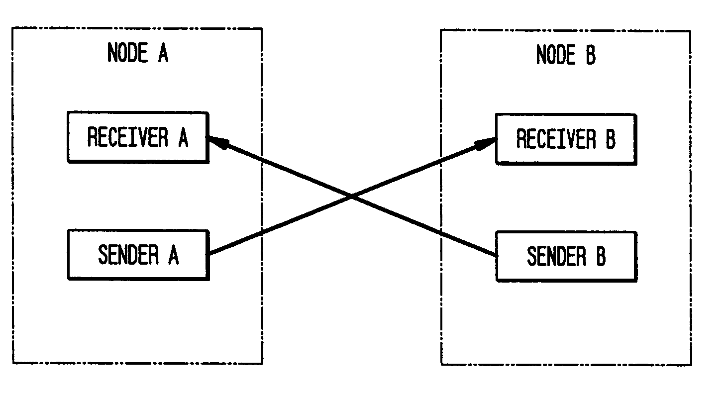
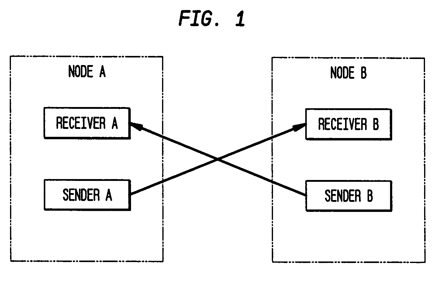
[0016]FIG. 1 shows two nodes A, B connected with a pair of cables. Receiver A and B are identical. Also sender A and B are identical. For simplicity, assume that the cables transfer one byte of data at each clock cycle. The communication protocol is packet based with byte-long packet headers that must be recognized by the receivers and trailers that contain some type of packet integrity check (such as checksum or CRC). When the receivers receive a special type of byte, called IDLE, they recognize it and do nothing further. If a header byte is not of known type, or if the packet integrity check fails, the receiver goes into an ERROR state. During normal operation, if there are no packets to be sent, the senders transmit IDLE and the receivers are in their normal WAIT state where they listen to incoming traffic.

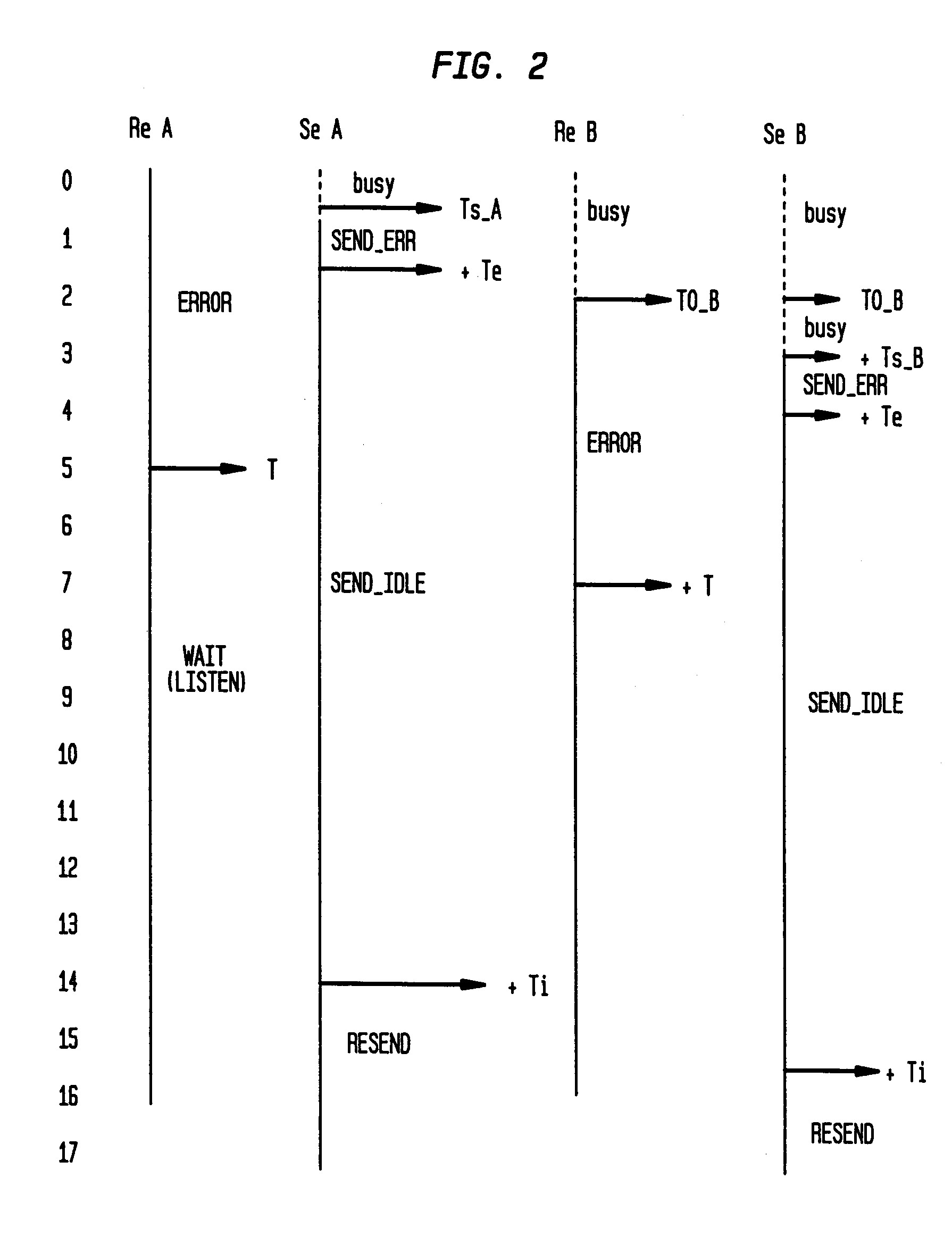
[0017]If either node gets an error (unknown header type or bad packet integrity check), the protocol of this invention ensures that at some later time both nodes will have thei...


PUM


Abstract

Disclosed are an error recovery method and system for use with a communication system having first and second nodes, each of said nodes having a receiver and a sender, the sender of the first node being connected to the receiver of the second node by a first cable, and the sender of the second node being connected to the receiver of the first node by a second cable. The method comprising the step of after one of the nodes detects an error, both of the nodes entering the same defined state. In particular, the receiver of the first node enters an error state, stays in the error state for a defined period of time T, and, after said defined period of time T, enters a wait state. Also, the sender of the first node sends to the receiver of the second node an error message for a defined period of time Te, and after the defined period of time Te, the sender of the first node enters an idle state.

Description

BACKGROUND OF THE INVENTION[0001]1. Field of the Invention[0002]This invention generally relates to the field of error recovery, and more particularly, the invention relates to a procedure that is very well suited for error recovery across long communication lines. Even more specifically, the invention relates to an error recovery protocol that is particularly well adapted for use with massively parallel computers used for various applications such as, for example, applications in the field of life sciences.[0003]2. Background Art[0004]FIG. 1 illustrates a pair of communication nodes A and B, each of which has a sender and a receiver. These two such nodes are connected with two cables. Each wire connects a sender / receiver pair. The cables may be long in the sense that a bit of data takes many clock cycles to traverse the cable. This type of hardware is encountered in many applications and most notably in massively parallel supercomputers.[0005]Obviously, as with any communication ch...

Claims


Application Information

Patent Timeline
Patent Type & Authority Patents(United States)
IPC IPC(8): G06F11/00G06F11/07G06F11/14H04L69/40
CPCG06F11/0709G06F11/0793G06F11/1443H04L1/0052H04L69/40H04L2001/0092H04L69/28
Inventor BLUMRICH, MATTHEW A.CHEN, DONGGARA, ALAN G.HEIDELBERGER, PHILIPHOENICKE, DIRK I.STEINMACHER-BUROW, BURKHARD D.VRANAS, PAVLOS M.
Owner INT BUSINESS MASCH CORP
Why Eureka
Try Eureka