Hubless caster

a hubless, caster technology, applied in the field of casters, can solve the problems of impairing the usability of the caster, inability to easily turn about the pin pivot, and the attachment of the wheel to the axle, so as to achieve the effect of improving rolling, improving the appearance of the caster, and virtually eliminating the friction of the lin

Inactive Publication Date: 2006-12-19
OCONOMOWOC MFG
View PDF15 Cites 29 Cited by
  • Summary
  • Abstract
  • Description
  • Claims
  • Application Information

AI Technical Summary

Benefits of technology

[0017]The present invention generally comprises a hubless caster device for use with furniture, equipment, carts, and other conveyances. This new device provides better stability, better rolling functionality, and many flexible design implementations.
[0019]The hubless caster shares some basic features with prior art caster designs: the central base component providing structure and a vertical pin, which attaches the central base component to the chair and allows the caster to pivot about the vertical pin. However, the present invention is unique in a very fundamental way, which provides great advantages over existing art. The device employs two wheels, each located at opposite ends of the base. The wheels are not disc shaped as is most common. Rather, the wheels are annular (doughnut shaped) with no central disk wall or any other structure inside the opening that extends through the annulus. Thus the largest, most visually dominant portion of the typical prior art designs is eliminated, The outside diameter of the wheel is circular and smooth, for efficient ground-engaging contact. The inside diameter is provided with a toroidal groove that is adapted to receive roller bearings, either cylindrical or ball type. The central base component includes a ring body, and two arrays of roller bearings are disposed at opposed sides of the ring body, each array engaging the groove of one of the wheels. The bearings support the wheels and permit rolling friction of the wheel about an axis defined by the centering ring portion of the base. The two wheels share a common ring body but do not share a common axle, bearings, nor support groove, so that each wheel is free to rotate independently. By eliminating the common center axle, the need for the center section of the base is obviated. Thus the wheels and the center base are open through-and through, greatly altering the visual appearance (compared to prior art designs) by permitting light to pass through the center of the caster assembly.
[0020]The use of rolling bearings allows better rolling as line friction has been virtually eliminated. Of course, bearings are very commonly used in wheel applications, mostly as ball bearings. However, in this invention the bearing arrangement differs in that the balls ride in grooves that are integral to the wheel and the base. Also, the bearings are not concentrated close to the axis of symmetry, as in central axle designs in the prior art, but are spaced apart near the outside diameter of the wheel where the wheel makes contact. This location provides a far more stable wheeled device in that any side loads (moment) are not transmitted via a lever arm (the radius of the wheel) further out to the center of rotation. The loads are transmitted to the bearings, which occupy a minimum space, thereby reducing the lever arm and providing less play in the system. Also, the grooves ‘capture’ the bearings very tightly (each ball surrounded by four planes). In this way, the balled joint has very little play and greatly reduces any wobble that occurs when a wheel is simply supported by an axle.
[0021]The elimination of the small diameter central axle enhances stability by virtue of the geometry of the mechanics of the assembly. Stiffness of a section is enhanced by geometry in which features are far from the center of neutral axis. (I.e., a pipe is stiffer than a rod if both are made of same material and employ same amounts of material.) With the wheels (via the bearings and centering ring) riding on the base directly (and not on an axle), the entire base becomes sole support for the wheels, with the enhanced effects of better stiffness and therefore a more stable overall device. Additionally, the base is far stronger than a simple axle and is more resilient to any impact on the device, hence it has better longevity.
[0022]The elimination of a central axle and the material that would normally surround it in the base provides the hubless caster with a distinct advantage over the existing art. This ‘hubless’ feature removes the visual prominence of the wheel and allows the base (in its simplified form) to be more apparent. This leads to greater opportunities to customize the caster by incorporating design elements of the overall design of the end device, such as a chair or furniture item or skateboard. If left open, the hubless caster will allow a skateboard or chair itself to appear to be ‘floating’. If desired, the central hubless area may be used to add features that are consistent and / or distinctive with the entire chair such as holes, cutouts, different colors, imprinted logos, reflective surfaces, translucent materials, similar materials, fabrics, and so on. The ease of customization will allow an infinite number of possible customizations to allow the hubless caster to be tailored for visual distinctiveness and design conformance with the overall aesthetic. This feature makes it very distinctive over the ubiquitous black twin wheeled caster.

Problems solved by technology

The main problem of the ‘single wheel’ caster is its inability to turn easily about the pin pivot.
These outside locations are unprotected from any collisions with other chairs or walls, often leading to a bent axle, which seriously impairs the usability of the caster.
One problem germane to this caster type is the method of attachment of the wheel to the axle.
This attachment configuration creates some inherent stability inefficiencies.
Also, the limited space remaining in the device for the wheel thickness results in thin wheels, which directly result in narrow annular (limited) bearing surfaces of the wheel on the axle.
The overall attachment of the wheel to the axle is inherently not completely stable.
With the simple method employing a pin (axle) in a hole (in the wheel), the resulting configuration is often fairly loose and sloppy.
Simply moving the wheels by hand shows the amount of ‘play’ in the assembly and lack of inherent design stability.
Both types of casters, additionally, suffer common drawbacks.
This type of friction is not as smooth and efficient as other types of motion.
Additionally, over time the friction removes material in the hole, creating a larger hole and subsequent ‘wobble’ as the tight fit in the axle is lost.
But for wheels whose primary purpose is to carry load and turn at very slow rotational speeds (5 rpm and often, for long periods of time, zero), the center axle is not ideal.
This moment adds more loading of the aforementioned wheel / axle joint, further decreasing the inherent stability of the overall device.
Finally, there is a common failing in casters of either of the common designs.
This leads to few opportunities to customize this type of caster for a specific chair design.

Method used


Image

  • Hubless caster
  • Hubless caster
  • Hubless caster

Examples


Embodiment Construction

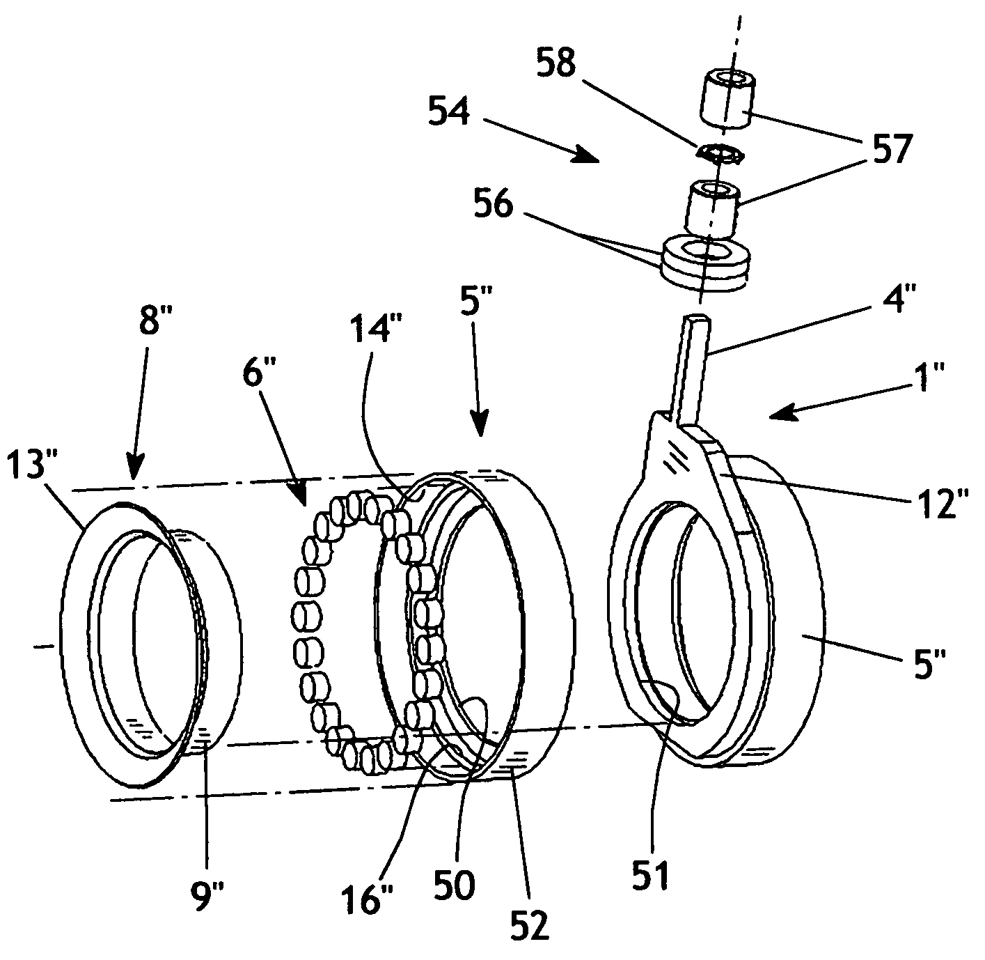
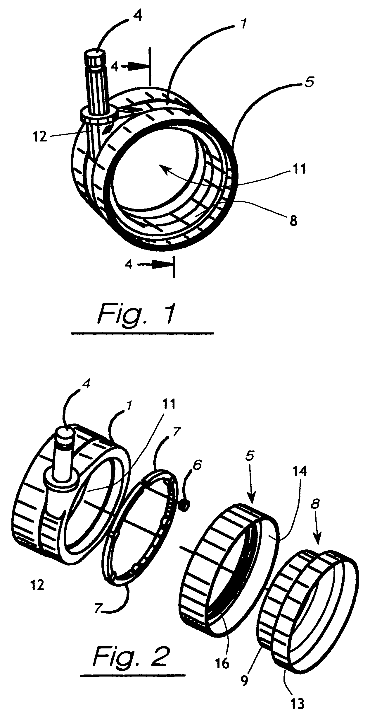
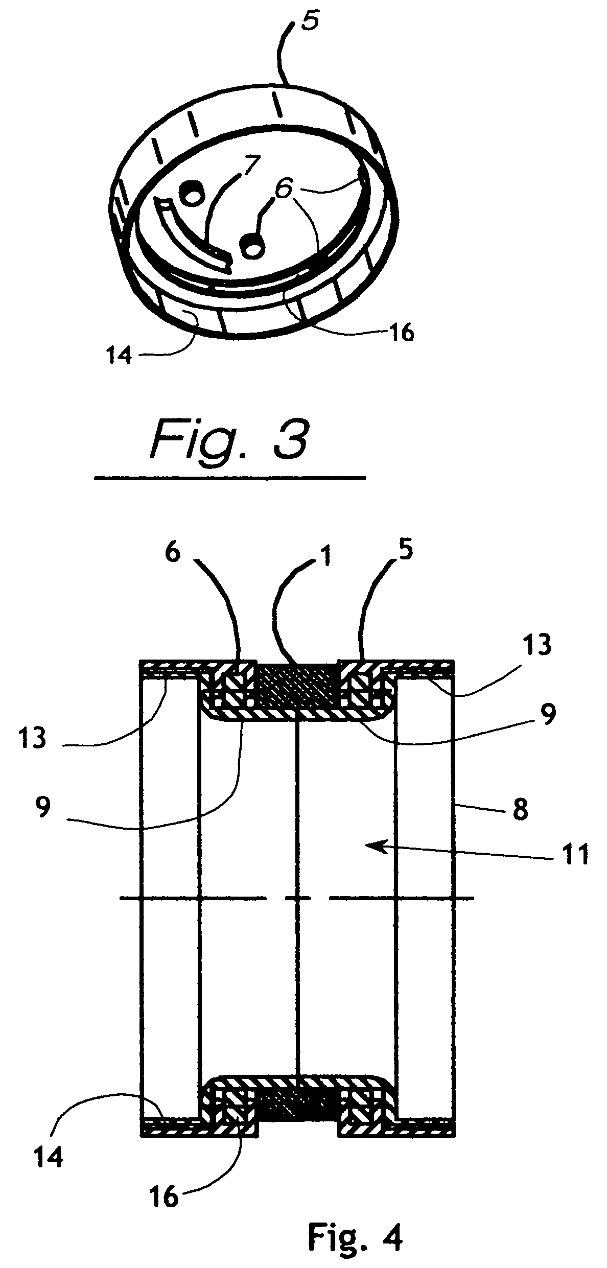
[0042]The present invention generally comprises a hubless caster assembly for use with furniture, equipment, carts, and other conveyances. This new device provides better stability, better rolling functionality, and many flexible design implementations.

[0043]With regard to FIGS. 1–4, the hubless caster assembly includes a ring body 1 having an open center portion 11. A kingpin 4 extends outwardly from the ring body 1 and is supported by an integral boss 12. (In the drawings, similar reference characters denote similar elements throughout the several views.) The kingpin may be received in a generally vertically oriented receptacle for pivoting motion about the kingpin axis, as is known in the prior art. The assembly also includes a centering ring 8, which is provided with an annular body 13 and a reduced diameter portion 9 extending coaxially from the body 13. A toroidal wheel 5 includes an outer surface adapted to be ground-engaging, and an inner annular surface 14. A bearing race g...


PUM


Abstract

A hubless caster assembly includes a caster body and at least one wheel, the wheel comprising a toroidal member having a bearing race, and a complementary bearing race supported by the caster body. Bearing elements in the races support the wheel in free rotation. The caster body may comprise a ring body having an axial opening, whereby the caster assembly has a large central aperture extending entirely therethrough. A centering ring may be secured in the axial opening with the complementary bearing race formed therein. A hub cap with visual treatment may be secured over the central aperture.

Description

CROSS-REFERENCE TO RELATED APPLICATIONS[0001]This application claims priority based on application Ser. No. 10 / 161,535, now U.S. Pat. No. 6,839,939, issued Jan. 11, 2005, which is based on U.S. Provisional Patent Application Ser. No. 60 / 295,592, filed Jun. 4, 2001.FEDERALLY SPONSORED RESEARCH[0002]Not applicable.SEQUENCE LISTING, ETC ON CD[0003]Not applicable.BACKGROUND OF THE INVENTION[0004]1. Field of the Invention[0005]The present invention relates generally to a caster and more specifically to a hubless caster for use in office furniture (chairs, tables, desks) as well as other devices or conveyances used primarily for transport of materials and pushed by hand (grocery carts, wagons). This new device is a caster that allows better inherent stability, easier rolling, and affords easy customization to enhance the overall aesthetic of the supported object (chair, table, cart, file cabinet, or other pieces of furniture). For the purpose of this patent, the attached device will assum...

Claims


Application Information

Patent Timeline
Patent Type & Authority Patents(United States)
IPC IPC(8): B60B33/00
CPCB60B3/048B60B7/061B60B33/001B60B33/0021B60B33/0028B60B33/0042B60B33/0049B60B33/0057B60B33/0068B60B33/0073B60B7/0053Y10T16/184Y10T16/18Y10T16/1847Y10T16/1853
Inventor DONAKOWSKI, WILLIAM J.
Owner OCONOMOWOC MFG
Why Eureka
Try Eureka