
Method and apparatus for riserless drilling

a technology of riserless drilling and drilling rigs, which is applied in the direction of drilling pipes, drilling/well accessories, sealing/packing, etc., can solve the problems of increasing the cost of drilling, increasing the weight and space requirements of the drilling rig and floating platform, and increasing the conventional method of riserless drilling

Inactive Publication Date: 2006-12-19
HALLIBURTON ENERGY SERVICES INC
View PDF32 Cites 42 Cited by
  • Summary
  • Abstract
  • Description
  • Claims
  • Application Information

AI Technical Summary

Benefits of technology

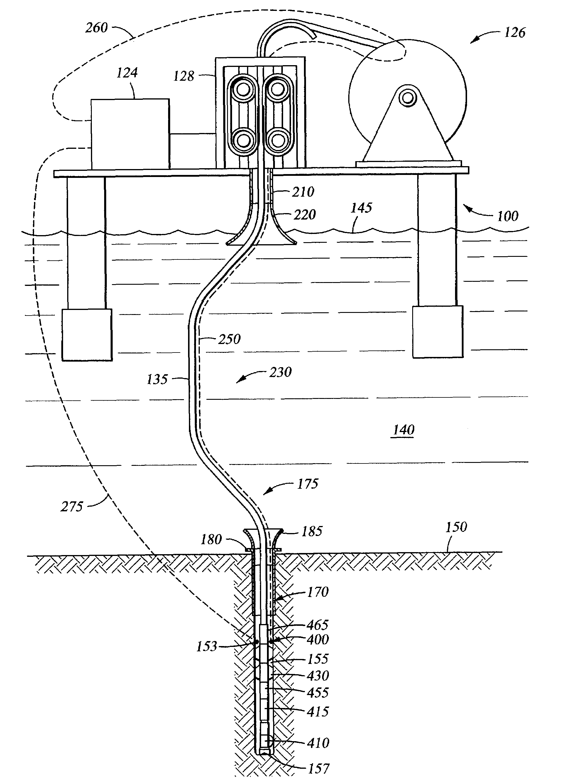
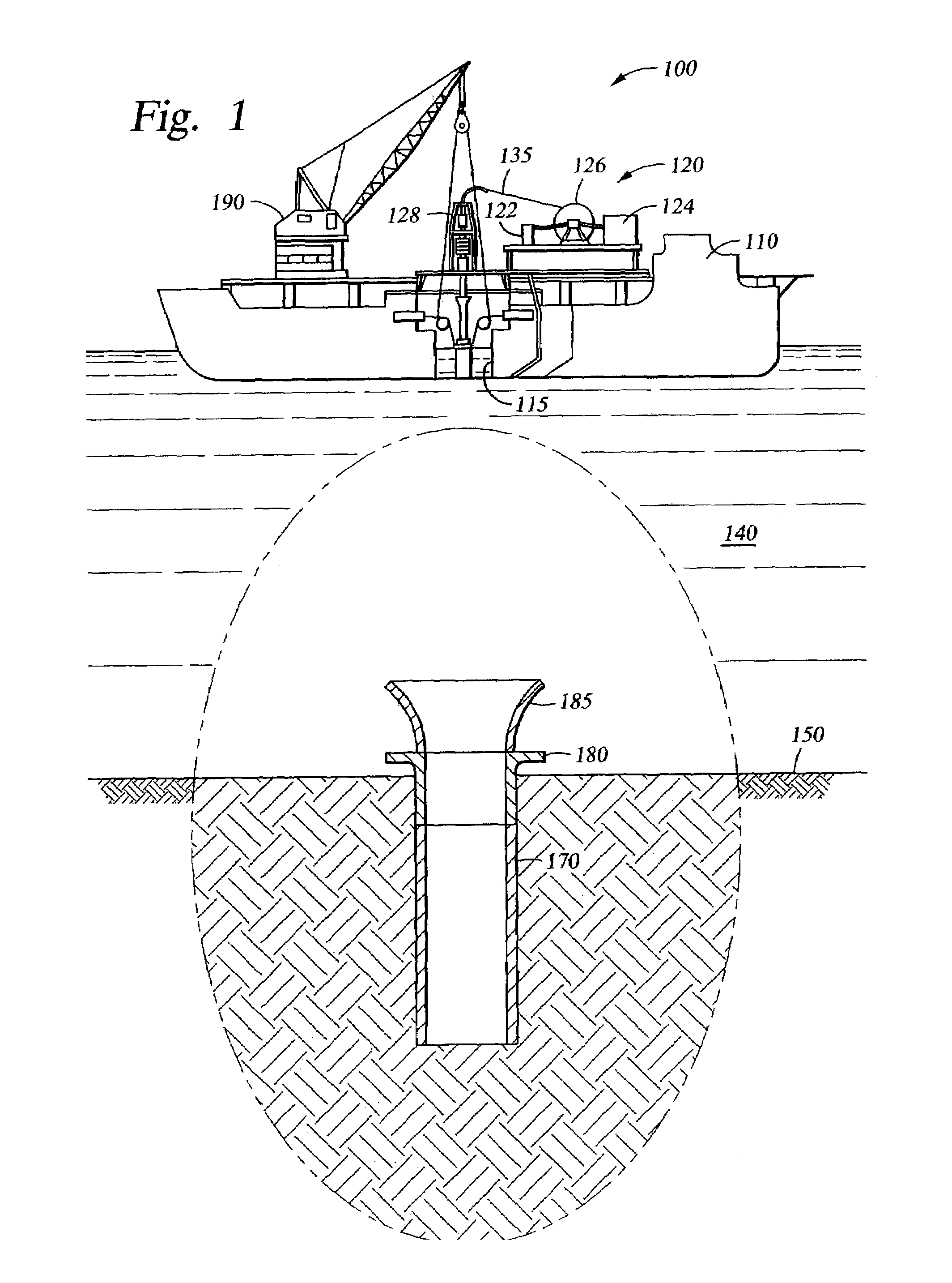
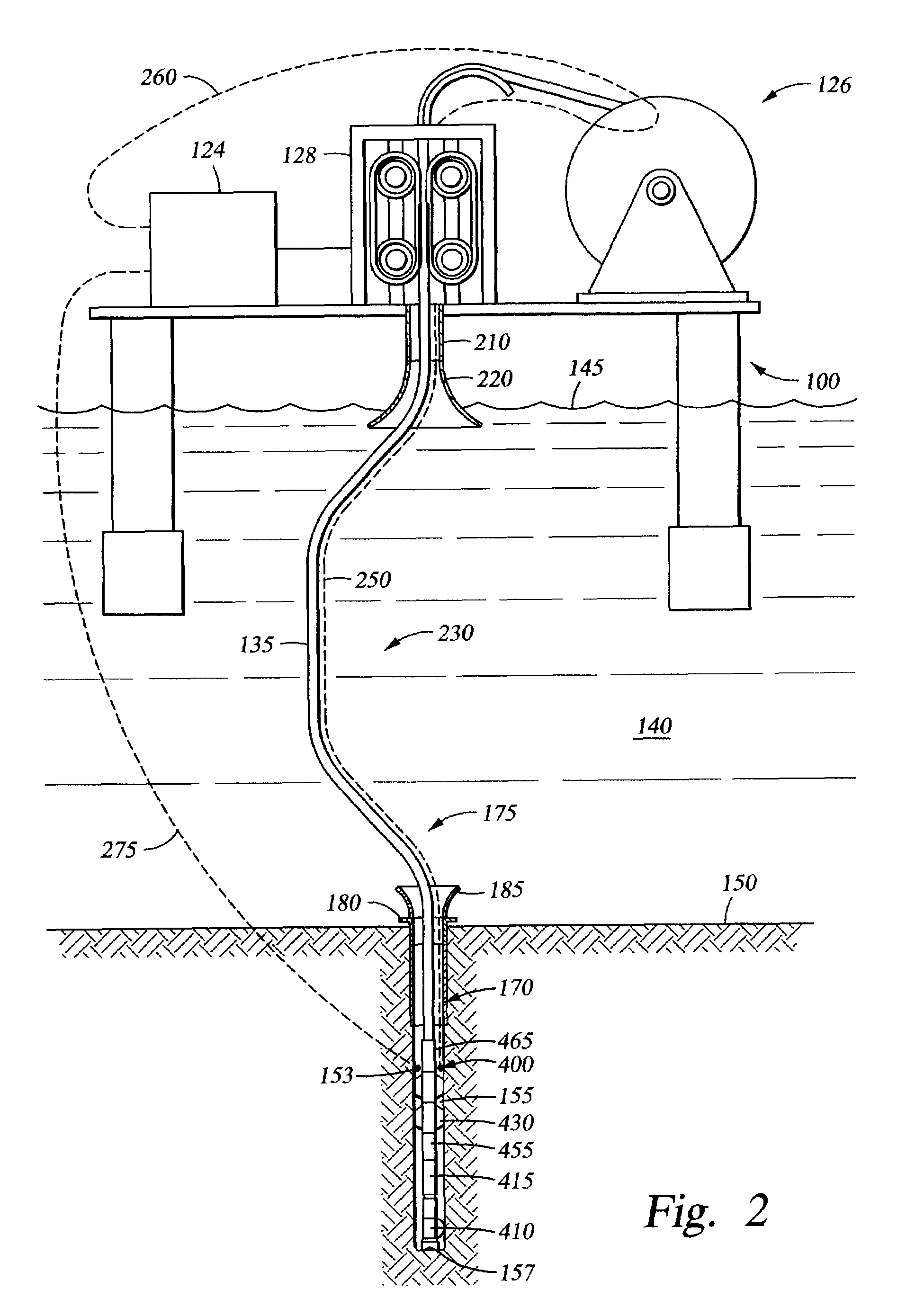
[0025]The present invention features improved methods and apparatus for the riserless drilling of a subsea wellbore. The preferred embodiments comprise a system for riserless drilling of a subsea borehole from a platform and through a cased borehole, the system comprising a lightweight drill string suspending a bottomhole assembly and extending from the platform downwardly through a depth of water into the cased borehole; a first limiter limiting the range of motion of the drill string adjacent the platform; and a second limiter limiting the range of motion of the drill string adjacent the cased borehole. In one embodiment, the bottomhole assembly includes a tension/compression sensor, and the system includes an injector that adjusts tension in the drill string in response to measurements made by the tension/compression sensor.
[0026]The preferred embodiments further comprise a method of drilling a subsea borehole from a platform and through a cased boreho

Problems solved by technology

However, this conventional method of riserless drilling has a number of disadvantages, especially when drilling from a floating platform in deep or ultra-deep waters.
Once the well reaches a certain depth, further drilling requires the use of a weighted drilling fluid to maintain control of downhole pressures, and such drilling fluids are costly enough to warrant returning the drilling fluid to the platform for cleaning so that the same drilling fluid may be recirculated for further drilling.
This conventional method of drilling with a riser from a platform has a number of disadvantages, especially when drilling from a floating platform in deep or ultra-deep waters.
First, the required size and capacity of the platform is largely based on the depth of water, and the corresponding amount of pipe required to drill the well.
The larger the pipe, and the more pipe required to form the riser, the greater the weight and space requirements of the drilling rig and floating platform.
Thus, as water depth increases, larger floating platforms are required for larger drilling rigs to handle and support the added weight of the pipe due to the greater depth and to store the additional pipe, thereby significantly increasing the costs of drilling as water depth increases.
Further, tripping into and out of the well with jointed pipe is very time-consuming since each joint of pipe must be threaded and / or unthreaded to the pipe string extending through the water and into the well.
However, as the drill string is made lighter, it becomes more susceptible to the effects of water currents.
The lighter the drill string, the more severe the effects.
Because water currents vary with depth and with time, and because the variability of the currents increases with increasing water depth, it is difficult to precisely predict deepwater currents and thus to design for their adverse effects.
Conventional riserless drilling systems and methods cannot be used with a lightweight drill string due to the conventional systems' inability to counteract the effects of the water currents on the lightweight drillstring.
As the weight of the drill string is reduced, it becomes less resistant to these undesirable effects of the water current, which can lead to unacceptably large bowing deflections and stresses in the drill string.
This upward force reduces weight-on-bit (WOB) and possibly lifts the bit off bottom, thereby preventing successful drilling.
Furthermore, as the weight of the drill strength is reduced and the water depth increases, the tendency of the drill string to kink increases, particularly at the floating platform and at the seafloor where the drill string is laterally constrained.
Thus, if the drill string bends too sharply, it will kink, and ultimately fail.

Method used


Image

  • Method and apparatus for riserless drilling
  • Method and apparatus for riserless drilling
  • Method and apparatus for riserless drilling

Examples


Embodiment Construction

[0038]The present invention is susceptible to embodiments of different forms. There are shown in the drawings, and herein will be described in detail, specific embodiments of the present invention with the understanding that the present disclosure is to be considered only an exemplification of the principles of the invention, and is not intended to limit the invention to that illustrated and described.

[0039]The apparatus and methods of the present invention comprise offshore drilling from a platform using a lightweight drill string suspending a BHA. Various embodiments of the present invention provide a number of different configurations of the drill string, the BHA, the type of platform from which drilling operations occur (i.e. bottom-founded or floating), the depth of the water, and the sizes of pipe components, such as risers and casings. It should be appreciated that the embodiments of the present invention, therefore, provide a plurality of methods for offshore drilling from a...


PUM


Abstract

An offshore riserless drilling system drills a subsea borehole from a platform and through a cased borehole. The system comprises a lightweight drill string suspending a bottomhole assembly and extending from the platform downwardly through a depth of water into the cased borehole; a first limiter limiting the range of motion of the drill string adjacent the platform; and a second limiter limiting the range of motion of the drill string adjacent the cased borehole. The preferred methods include lowering a bottomhole assembly suspended on a lightweight drill string from a platform through a depth of water; limiting the bend radius of the drill string adjacent the platform; guiding the bottomhole assembly into a cased borehole; limiting the bend radius of the drill string adjacent the cased borehole; maintaining the bottomhole assembly in the cased borehole, and drilling the subsea borehole.

Description

CROSS-REFERENCE TO RELATED APPLICATIONS[0001]The present application is related to application Ser. No. 10 / 265,028, filed Oct. 4, 2002 and entitled Methods and Apparatus for Open Hole Drilling, hereby incorporated herein by reference in its entirety.STATEMENT REGARDING FEDERALLY SPONSORED RESEARCH OR DEVELOPMENT[0002]Not Applicable.BACKGROUND OF THE INVENTION[0003]1. Field of the Invention[0004]The present invention relates generally to methods and apparatus for performing riserless drilling from an offshore platform, and more particularly, to methods and apparatus for performing riserless drilling using a lightweight drill string, and still more particularly, to methods and apparatus for drilling an offshore well from a platform using a lightweight, small diameter, continuous drill string thereby enabling the use of comparatively smaller diameter pipe components and a smaller platform versus conventional methods.[0005]2. Description of the Related Art[0006]Offshore hydrocarbon dril...

Claims


Application Information

Patent Timeline
IPC IPC(8): E21B29/12E21B7/128E21B19/24
CPCE21B7/128E21B19/24
Inventor LAURSEN, PATRICK EMMETTMUNGALL, JOHN CHRISTIAN HARTLEY
Owner HALLIBURTON ENERGY SERVICES INC
Learn More