Method for interconnecting adjacent expandable pipes

a technology of expandable pipes and interconnections, which is applied in the direction of manufacturing tools, mechanical equipment, and well accessories, etc., can solve the problems of inability to meet the safety requirements of tig welding, inability to conduct electrical resistance welding (erw), and inability to meet the safety requirements

Inactive Publication Date: 2006-12-19
SHELL USA INC
View PDF22 Cites 28 Cited by
  • Summary
  • Abstract
  • Description
  • Claims
  • Application Information

AI Technical Summary

Benefits of technology

[0011]The expressions “pipe” and “pipes” as used in the text and claims of this application refer to tubular elements of various lengths and various wall thickness. For instance, relatively short pipe sections may be used of average length 6.7 m (API range 1)

Problems solved by technology

However, either method has its drawbacks.
Unfortunately, safety requirements do not generally allow TIG welding at or near the borehole.
Another form of welding, electrical resistance welding (ERW) is unacceptable for the same reason.
Welding at the rig floor therefore seems to be too risky.
On the other hand, threaded connections are not gas tight, especia

Method used


Image

  • Method for interconnecting adjacent expandable pipes
  • Method for interconnecting adjacent expandable pipes
  • Method for interconnecting adjacent expandable pipes

Examples


experiment 1

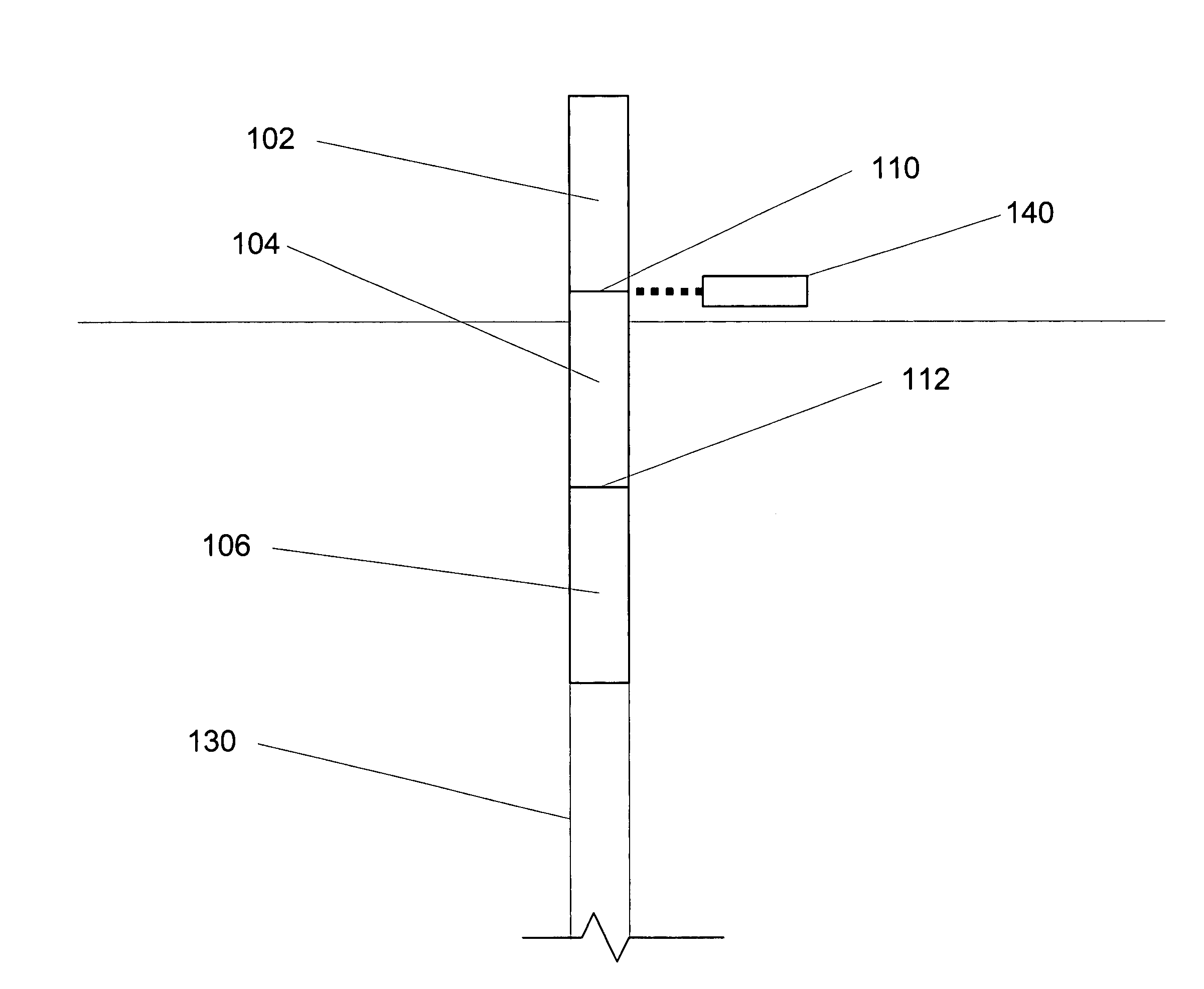
[0045]Casings of two different materials, API J-55 and L-80 material, and three different sizes, nominal outside diameter of 5 inch, 5.5 inch 4.5 inch, were laser welded using an Nd:YAG laser. J-55 is a material having a min. yield strength of 55.000 psi; a max. yield strength of 80.000 psi; and a min. tensile strength of 75.000 psi. L-80 is a material having a min. yield strength of 80.000 psi; a max. yield strength of 95.000 psi; and a min. tensile strength of 95.000 psi. The laser welds of these products were evaluated and found to produce gas-tight connections. In these experiments the welds were found to have the toughness of the base material in both the longitudinal and transverse orientation. Toughness was even improved (resulting in a better and more consistent weld) when the welds were subjected to post weld stress relief.


PUM

PropertyMeasurementUnit
Lengthaaaaaaaaaa
Distanceaaaaaaaaaa
Energyaaaaaaaaaa

Abstract

The present invention relates to a method for interconnecting adjacent expandable pipes by Laser Beam Welding (LBW).

Description

FIELD OF THE INVENTION[0001]The present invention relates to a method for interconnecting adjacent expandable pipes.BACKGROUND OF THE INVENTION[0002]International applications WO 93 / 25799 (which issued as U.S. Pat. No. 5,348,095), WO 98 / 00626 (which was filed as U.S. patent application Ser. No. 08 / 891,318) and WO 99 / 35368 (which was filed as U.S. patent application Ser. No. 09 / 223,996), the contents of which are incorporated by reference, concern the so-called ‘expandable-tube technology’ for well construction and wellbore repair. In short, this technology involves lowering a pipe (also referred to as ‘oilfield tubular’) of a malleable steel grade material into a borehole or existing casing, followed by an expansion process (e.g. by moving an expansion mandrel or pig through the pipe). The pipe may serve as a casing, or as a production tubing (liner) through which a hydrocarbon product is transported to the surface. Alternatively, the pipe may be expanded against the inner surface o...

Claims


Application Information

Patent Timeline
IPC IPC(8): E21B19/16B23K26/00E21B43/10
CPCE21B43/103E21B43/106
Inventor MARKETZ, FRANZSTEWART, ROBERT BRUCE
Owner SHELL USA INC
Why Eureka
Try Eureka