Speed controller for a vehicle

a technology of speed controller and vehicle, which is applied in the direction of electric propulsion mounting, transportation and packaging, propulsion unit arrangement, etc., can solve the problems of serious safety problems and injury to drivers, unsuitable or possible for drivers with physical limitations, and it is not possible to turn the pedals and crank mechanisms forward without substantial muscular effort to propel the vehicle. to achieve the effect of improving operator control

Inactive Publication Date: 2006-12-19
EDMONDS JR RICHARD F
View PDF15 Cites 8 Cited by
  • Summary
  • Abstract
  • Description
  • Claims
  • Application Information

AI Technical Summary

Problems solved by technology

However, these types of speed controllers or throttles can jam or stick in a fixed position, continuing the delivery of power when it is not wanted.
This can cause serious safety problems and injury to the driver.
Kinematic type drives which require the constant activity of the operator such as a pedal and crank arrangement commonly found on power-assisted bicycles also require substantial muscle power of the operator to drive the vehicle which may not be desirable or possible for drivers with physical limitations.
In all instances, however, the pedal crank mechanism is positively linked to the drive wheel by a chain and sprockets, and it is not possible to turn the pedals and crank mechanism forward without substantial muscular effort required to propel the vehicle.
Since these vehicles can always be muscle-powered, there is no way to electrically disable them to limit their use as may be desired for a child's toy vehicle or to prevent unauthorized use.

Method used


Image

  • Speed controller for a vehicle
  • Speed controller for a vehicle
  • Speed controller for a vehicle

Examples


Embodiment Construction

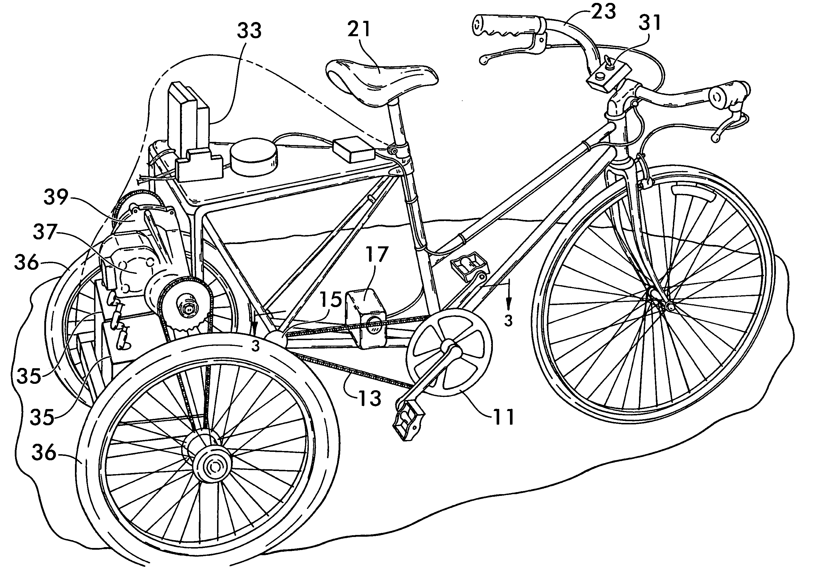
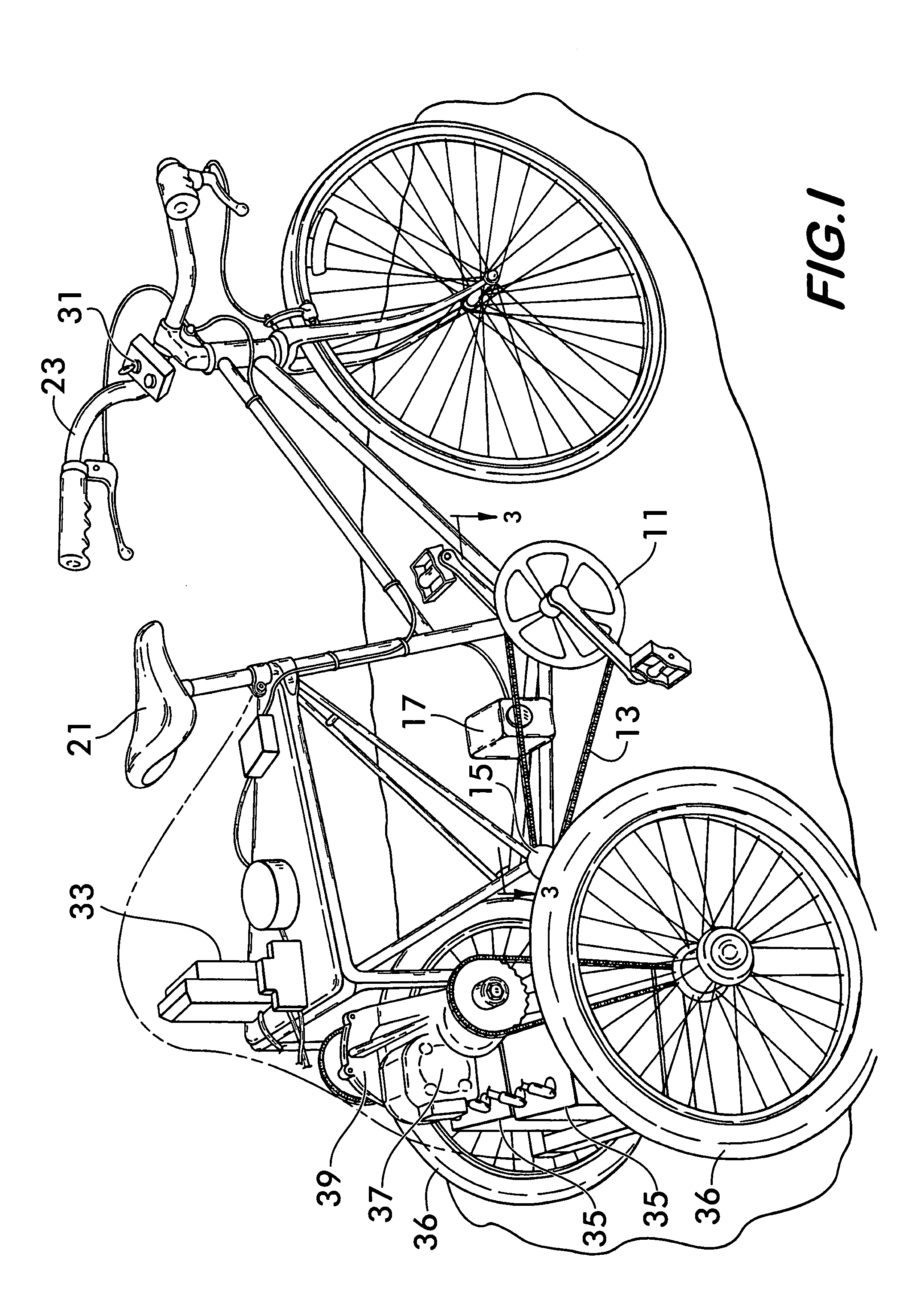
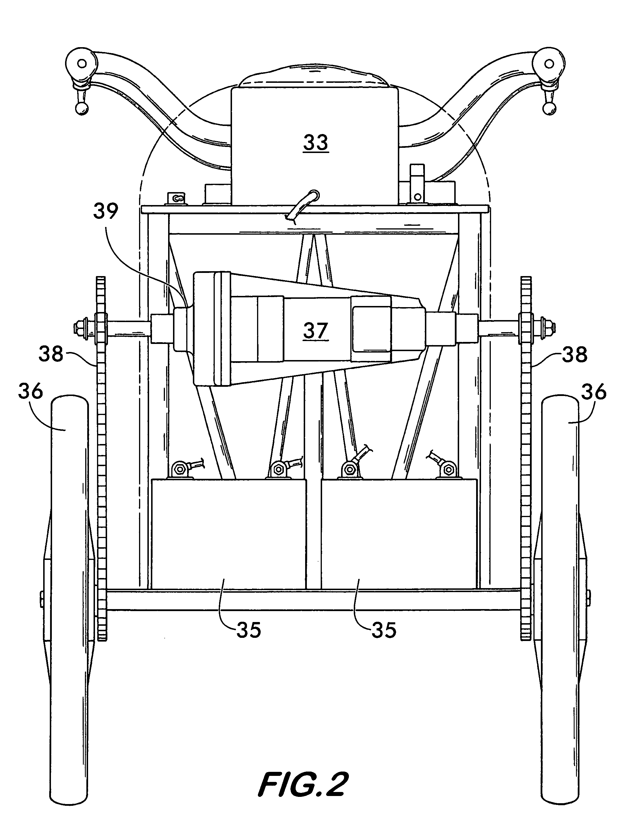
[0014]Referring now to FIG. 1, one embodiment of the invention may be employed as a three-wheeled tricycle. A bicycle-type crank and pedal assembly 11 is included in this embodiment which pulls chain 13 that is connected to an idler sprocket 15. The top run of the chain drives a generator 17, the electrical output of which increases as the speed of the crank and pedal assembly increases. This assembly together with the seat 21 and handle bar assembly 23 complete a configuration of a three-wheeled vehicle which is simulative of a pedaled tricycle. The present invention, however, is purely motor driven with the crank and pedal drive means being mechanically independent of the motor drive.

[0015]The electrical circuitry of the drive means will be described in more detail with regard to FIGS. 4 and 5, but generally includes the following major components shown in this figure, namely on / off switch means 31, generator 17 which is responsive to the speed of the crank assembly having an elec...


PUM


Abstract

A kinematic speed controller for a vehicle requires the constant deliberate movement of a rotary apparatus which is physically independent from the vehicle drive system. It does not require substantial operator muscle power since there is no direct mechanical connection between the kinematic controller and the vehicle drive system. The rotary apparatus which controls the vehicle speed may be a foot pedal and crank assembly. Additionally, the invention may include a variable degree of resistance to the rotary input device to enhance operator control or to provide muscle exercise for the operator if desired. Furthermore, the invention may include the variable setting of the relationship between the speed of the rotary input device and the amount of power provided to drive the vehicle and hence the speed of the vehicle. The components of the invention may be arranged to visually simulate a bicycle-type mechanical chain drive. The speed controller is preferably connected to an electrical generator which through appropriate circuitry controls the amount of power delivered to a drive motor from batteries. A simple electrical key switch may be utilized to completely disable the operation of the vehicle.

Description

FIELD OF THE INVENTION[0001]This invention relates to a speed controller for a powered vehicle. More specifically, it relates to a rotary speed control for a vehicle simulative of a bicycle-type sprocket and chain drive.BACKGROUND OF THE INVENTION AND PRIOR ART[0002]There are many different types of speed controllers for powered vehicles which are usually either hand levers or foot pedals such as an automobile accelerator pedal. These devices provide a fixed position of the lever or pedal which corresponds to an amount of power delivered to propel the vehicle. Some are mechanically independent, so-called “drive-by-wire” devices. However, these types of speed controllers or throttles can jam or stick in a fixed position, continuing the delivery of power when it is not wanted. This can cause serious safety problems and injury to the driver. Kinematic type drives which require the constant activity of the operator such as a pedal and crank arrangement commonly found on power-assisted b...

Claims


Application Information

Patent Timeline
Patent Type & Authority Patents(United States)
IPC IPC(8): B62M23/02B62M6/60B62M6/45
CPCB62M6/45B62M6/60
Inventor EDMONDS, JR., RICHARD F.
Owner EDMONDS JR RICHARD F
Why Eureka
Try Eureka