Transportation and power generating system of gravity and leaf springs

a technology of gravity and power generating system, which is applied in the direction of mechanical energy handling, mechanical equipment, mechanical devices, etc., can solve the problems of prior art devices that cannot generate electric power at constant rate, and cannot provide portable power generation devices having small sizes, etc., to achieve simple and easy use and maintenance, and low manufacturing cost

Inactive Publication Date: 2006-12-19
ESKANDR ASHRAF MAKRM DAWOUD
View PDF14 Cites 33 Cited by
  • Summary
  • Abstract
  • Description
  • Claims
  • Application Information

AI Technical Summary

Benefits of technology

[0021]Another object of the present invention is to provide a system for conversion the mechanical energy of two assemblages of strained leaf springs to rotary motion to drive an airplane, a car, and a ship instead of using any weight to be this system having light weight and great output.
[0023]Another object of the present invention is to provide a system can combine with a second system by using a crankshaft to form one system can generate constant output for driving a heavy truck; and also to provide a system its brake device can be connected with a hydraulic or an air line of the brake of that truck for convenience driving, because, driver does not need using a clutch's pedal to decrease the speed.
[0025]Further object of the present invention is to provide a system that is simple and easy to use and maintain.
[0026]An object of the present invention is to provide a system that is economical in cost to manufacture.

Problems solved by technology

The prior art can not provide a power generating device having a portable small size to convert the gravity to rotary motion for production electricity.
The prior art uses variable power input from solar energy, wind energy, sea-wave energy, and passing vehicles on the road for generation electricity, therefore, the devices of the prior art can not generating electric power with constant rate at any time of the year.

Method used


Image

  • Transportation and power generating system of gravity and leaf springs
  • Transportation and power generating system of gravity and leaf springs
  • Transportation and power generating system of gravity and leaf springs

Examples


Embodiment Construction

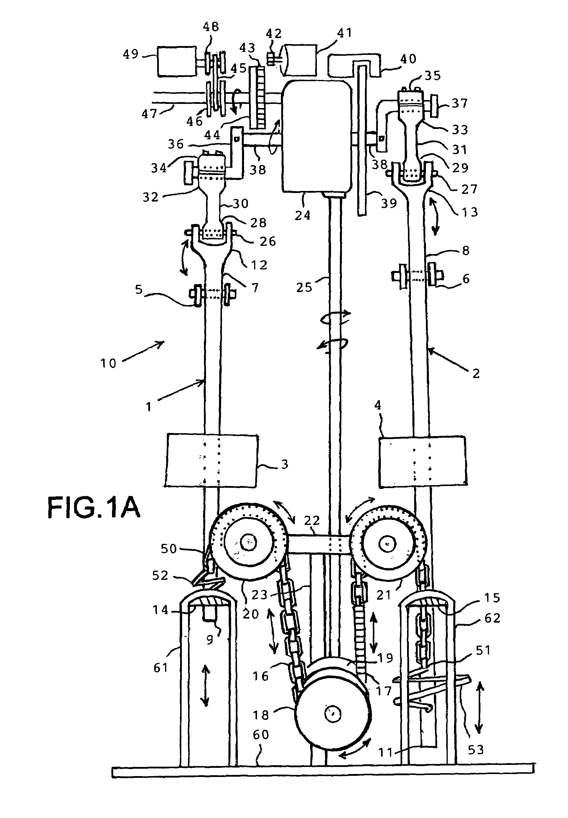
[0051]Please Refer to FIG. 1a.

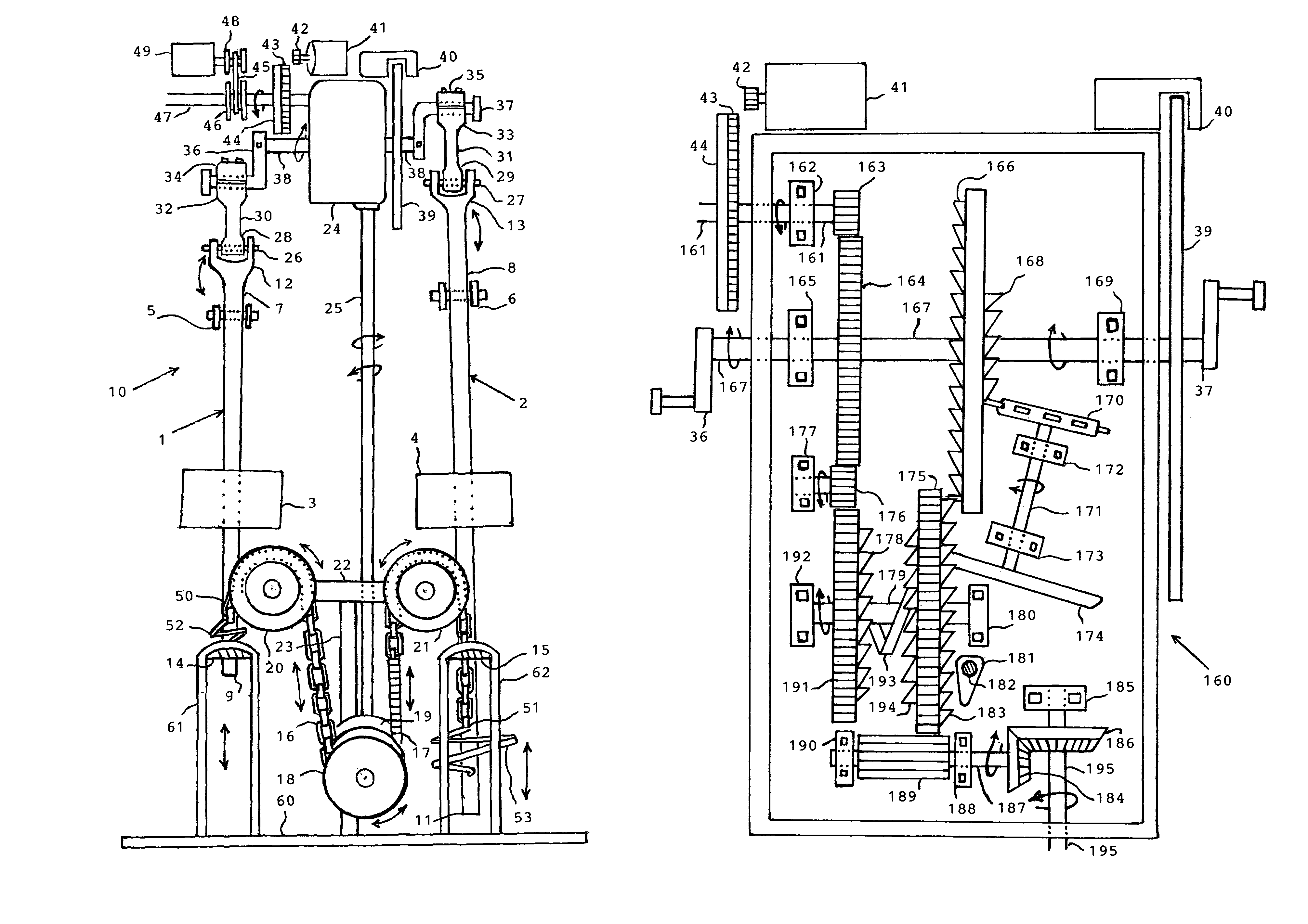
[0052]FIG. 1a is a perspective diagram showing an upper part of a preferred embodiment for generating kinetic energy by gravity according to the present invention. A transportation and power generating system of gravity and leaf springs 10 includes: two identical beams 1 and 2 for conversion potential energy of two weights 3 and 4 to oscillatory movement can be converted into rotary motion of a crankshaft 38 by two traces 30 and 31; a gearbox 24 is shown in FIG. 7a for regulation oscillatory movement of two beams 1 and 2 through a shaft 25, two pulleys 18 and 19, two chains 16 and 17; an electric starter 41 for starting the system; and a frame 60 for fixing a gearbox 24, a frame 5, a frame 6, a vertical frame 23, a frame 61, a frame 62, and an alternator 49 thereon. Two identical weights 3 and 4. A Y-shaped frame 5 for pivoting the beam 1. A Y-shaped frame 6 for pivoting the beam 2. An end 7 of the beam 1. An end 8 of the beam 2. An end 9 of the beam 1...


PUM


Abstract

Two weights and or springs mounted on two pivoted beams. A short end of each beam is interconnected with a gearbox by a crank and trace. The gearbox is interconnected with two other ends of the beams by linkages. An electric starter with battery imparts kinetic energy to lift one weight and let the other weight descend. The gearbox regulates the oscillation of two beams. The operator turns the electric starter off after the system is started. An output shaft imparts rotary motion of the gearbox to drive a vehicle, an airplane, or an AC generator.

Description

BACKGROUND OF THE INVENTION[0001]The present invention relates to a mechanical system for generating rotary motion of gravity and strained leaf springs for driving a small car, a bus, a ship, and an air plane and also generation electricity by an AC generator.[0002]The prior art as in the following patents:[0003]U.S. Pat. No. 507,289 issued on Sep. 19, 1974 class 290 / 53 to Rusbey; Joseph V. A tide-powered electrical generator wherein the energy from successive rising tides is stored in the form of potential energy for selective conversion to electricity. A float is constrained to vertical motion and it raises on successive tide a weight by means of a jack bar to reach a maximum predetermined high on a stable support structure where the weight is supported until release for the generation of electricity. Provision is made for the prevention of damage to the generator by excessive tidal rises.[0004]U.S. Pat. No. 670,697 class 185 / 30 issued on Mar. 26, 1976 to Schera, Jr.; Enos L. A sh...

Claims


Application Information

Patent Timeline
Patent Type & Authority Patents(United States)
IPC IPC(8): F02B63/04F03G7/08H02K7/18
CPCF03G1/00F03G3/00F03G7/10H02K53/00F03G1/02
Inventor ESKANDR, ASHRAF MAKRM DAWOUD
Owner ESKANDR ASHRAF MAKRM DAWOUD
Why Eureka
Try Eureka