Raman amplification repeater

a repeater and amplification technology, applied in electromagnetic repeaters, transmission monitoring, instruments, etc., can solve the problem that the power of excitation light cannot be controlled externally after, and achieve the effect of expanding the signal bandwidth of transmitted signal ligh

Inactive Publication Date: 2006-12-19
NEC CORP
View PDF9 Cites 4 Cited by
  • Summary
  • Abstract
  • Description
  • Claims
  • Application Information

AI Technical Summary

Benefits of technology

[0010]An object of the present invention is to provide a Raman amplification repeater which enables the power of excitation light to be adjusted externally and which allows for an attempt to expand the signal bandwidth of transmitted signal light even after the transmission system is established.

Problems solved by technology

These conventional Raman amplification repeaters described above have a problem that the power of excitation light cannot be controlled externally after the transmission system is established.
There is also a problem that the signal bandwidth of signal light to be transmitted is defined in a narrow range, since the center wavelength of excitation light that is input into a transmission line fiber is set in a fixed manner.

Method used


Image

  • Raman amplification repeater
  • Raman amplification repeater
  • Raman amplification repeater

Examples


Embodiment Construction

[0036]The preferred embodiment of the present invention will be discussed hereinafter in detail with reference to the accompanying drawings. In the following description, numerous specific details are set forth in order to provide a thorough understanding of the present invention. It will be obvious, however, to those skilled in the art that the present invention may be practiced without these specific details. In other instance, well-known structures are not shown in detail in order to unnecessary obscure the present invention.

[0037]The preferred embodiments of the present invention will now be described in detail by referring to the drawings.

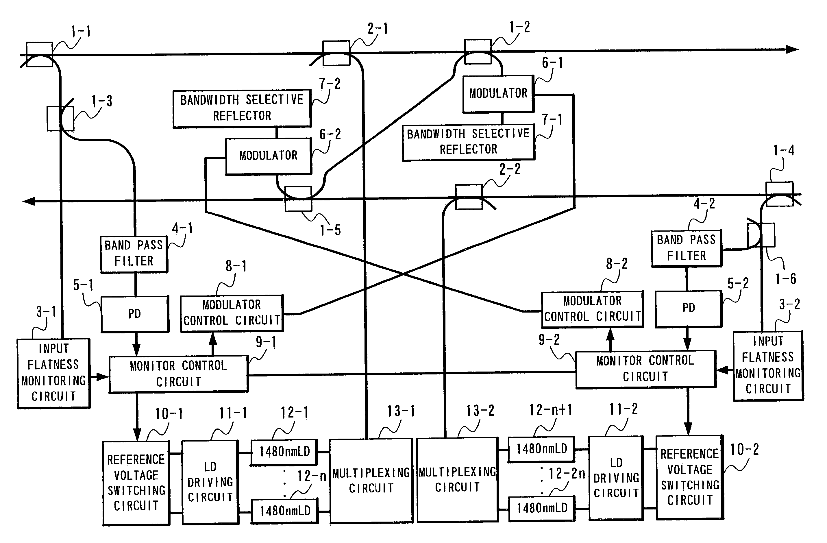
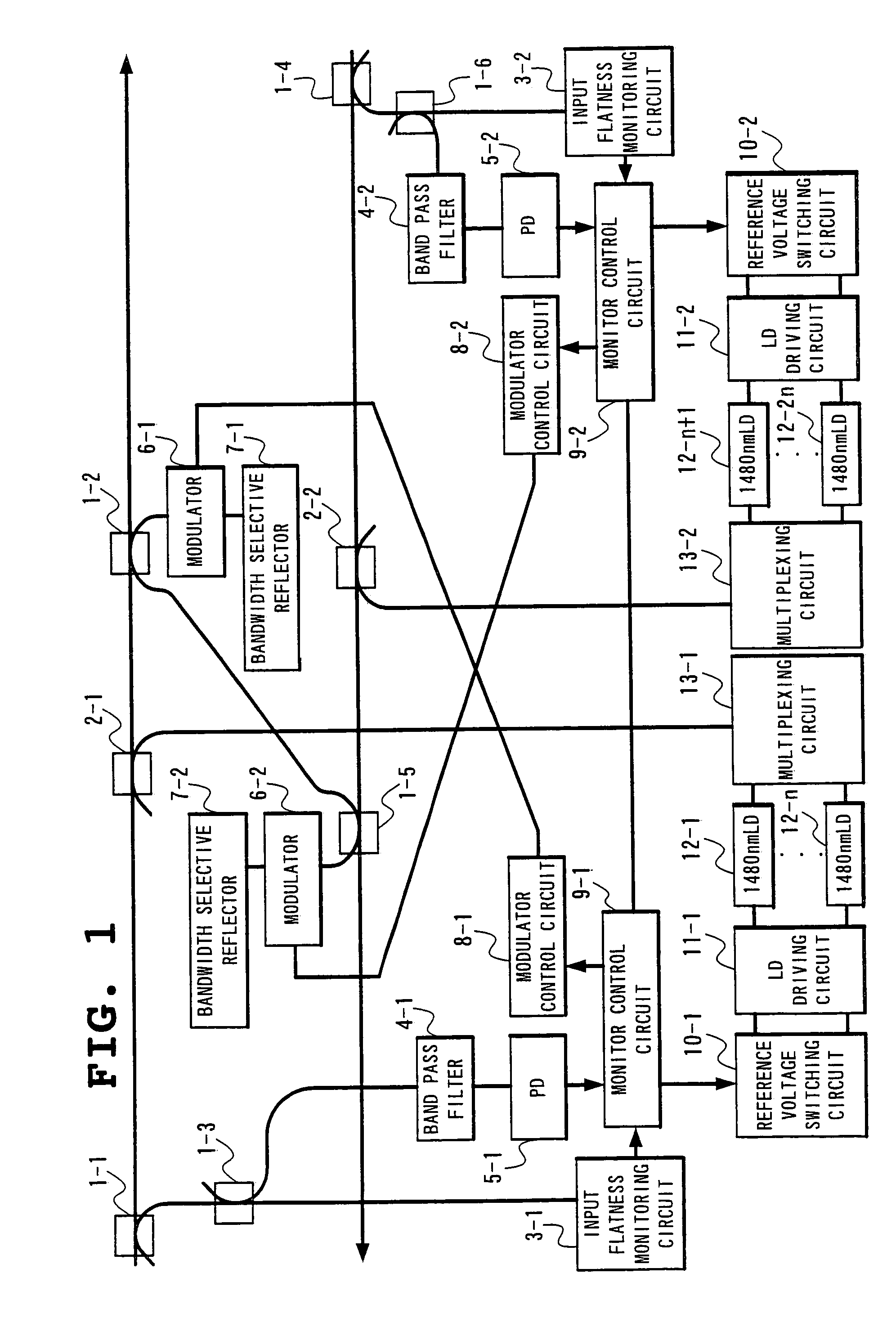
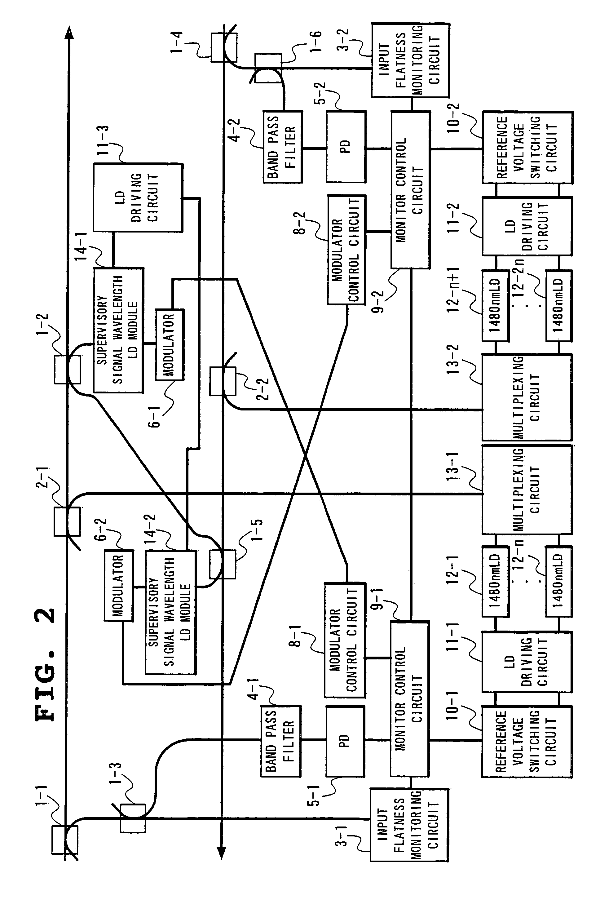
[0038]FIG. 1 shows the configuration of a Raman amplification repeater according to the first embodiment of the present invention. The Raman amplification repeater according to this embodiment, shown in FIG. 1, is of the same configuration between upstream and downstream directions, and includes upstream branch couplers 1-1, 1-2, 1-3 and downs...


PUM

PropertyMeasurementUnit
flatnessaaaaaaaaaa
center wavelengthsaaaaaaaaaa
wavelength rangeaaaaaaaaaa

Abstract

A repeater according to the present invention includes a plurality of excitation light sources with varying center wavelengths for use as an excitation light source to achieve Raman amplification; and comprises a flatness monitoring circuit which monitors the flatness of signal light on a transmission line; a monitor control circuit which controls externally said excitation light sources based on a remote supervisory control signal and which determines which of said excitation light sources to control as appropriate according to the flatness of signal light identified by said flatness monitoring circuit; and a bandwidth selective reflector or LD modules which, under the control of said monitor control circuit, outputs said flatness information to another repeater as a remote supervisory control signal with a specific wavelength, via said transmission line.

Description

BACKGROUNDS OF THE INVENTION[0001]1. Field of the Invention[0002]The present invention relates to a Raman amplification repeater which utilizes amplification of signal light by Raman scattering that occurs when an excitation LD is input into a transmission line fiber. In particular, the present invention relates to a Raman amplification repeater which enables expansion of a signal bandwidth and external control of Raman amplification.[0003]2. Description of the Related Art[0004]The recent advancement of wavelength multiplexing technology has allowed current transmission systems to multiplex a wavelength into many, generating the necessity of repeaters (e.g., submarine repeaters) with wider bandwidths than in the past. Raman amplification is a technique effective in achieving a wider bandwidth in repeaters, and studies have actively been addressed to develop a repeater based on this technique. This repeater, called a “Raman amplification repeater,” utilizes amplification of signal li...

Claims


Application Information

Patent Timeline
Patent Type & Authority Patents(United States)
IPC IPC(8): H01S3/30G02F1/35H04B10/077H04B10/079H04B10/29H04B10/294H04B10/297H04B17/00
CPCH04B10/0775H04B10/2916H04B2210/077H04B2210/078
Inventor YAMAGUCHI, SHOHEI
Owner NEC CORP
Why Eureka
Try Eureka