Dielectric recording/reproducing head and dielectric recording/reproducing apparatus

a recording/reproducing head and dielectric technology, applied in the field of dielectric recording/reproducing head, dielectric recording apparatus, dielectric reproducing apparatus, can solve the problems of high-speed reading, limited recording density, and relatively large pickup, and achieve the effect of increasing the recording capacity

Inactive Publication Date: 2006-12-19
YASUO CHO +1
View PDF8 Cites 16 Cited by
  • Summary
  • Abstract
  • Description
  • Claims
  • Application Information

AI Technical Summary

Benefits of technology

[0009]It is therefore an object of the present invention to provide a dielectric recording / reproducing head, a dielectric recording apparatus, a dielectric reproducing apparatus, or a dielectric recording / reproducing apparatus, capable of multivalued or multilevel recording by forming polarization domains having polarization directions parallel to a surface of a dielectric recording medium in order to increase its recording capacity, with respect to data recording or data reproduction using the SNDM method.

Problems solved by technology

However, the pickup is relatively large, which is inappropriate for high-speed reading.
However, the recording density is limited to 1 T bit / inch2 because of thermal fluctuation of magnetic recording information and the presence of a Bloch wall in a portion in which a code is reversed, even if patterned media are used in view of the above cause.

Method used


Image

  • Dielectric recording/reproducing head and dielectric recording/reproducing apparatus
  • Dielectric recording/reproducing head and dielectric recording/reproducing apparatus
  • Dielectric recording/reproducing head and dielectric recording/reproducing apparatus

Examples


Embodiment Construction

(Embodiment of Dielectric Reproducing / Reproducing Head)

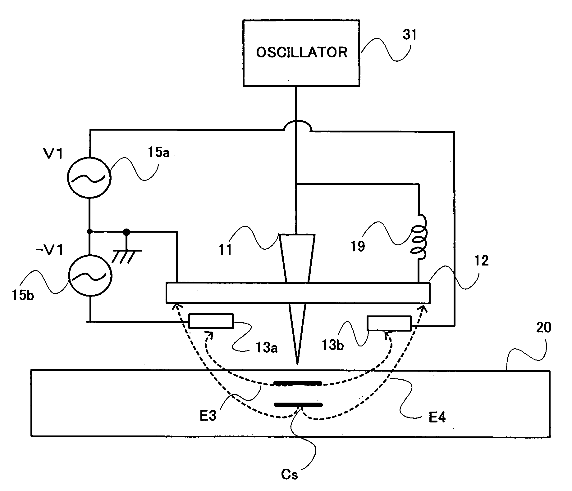
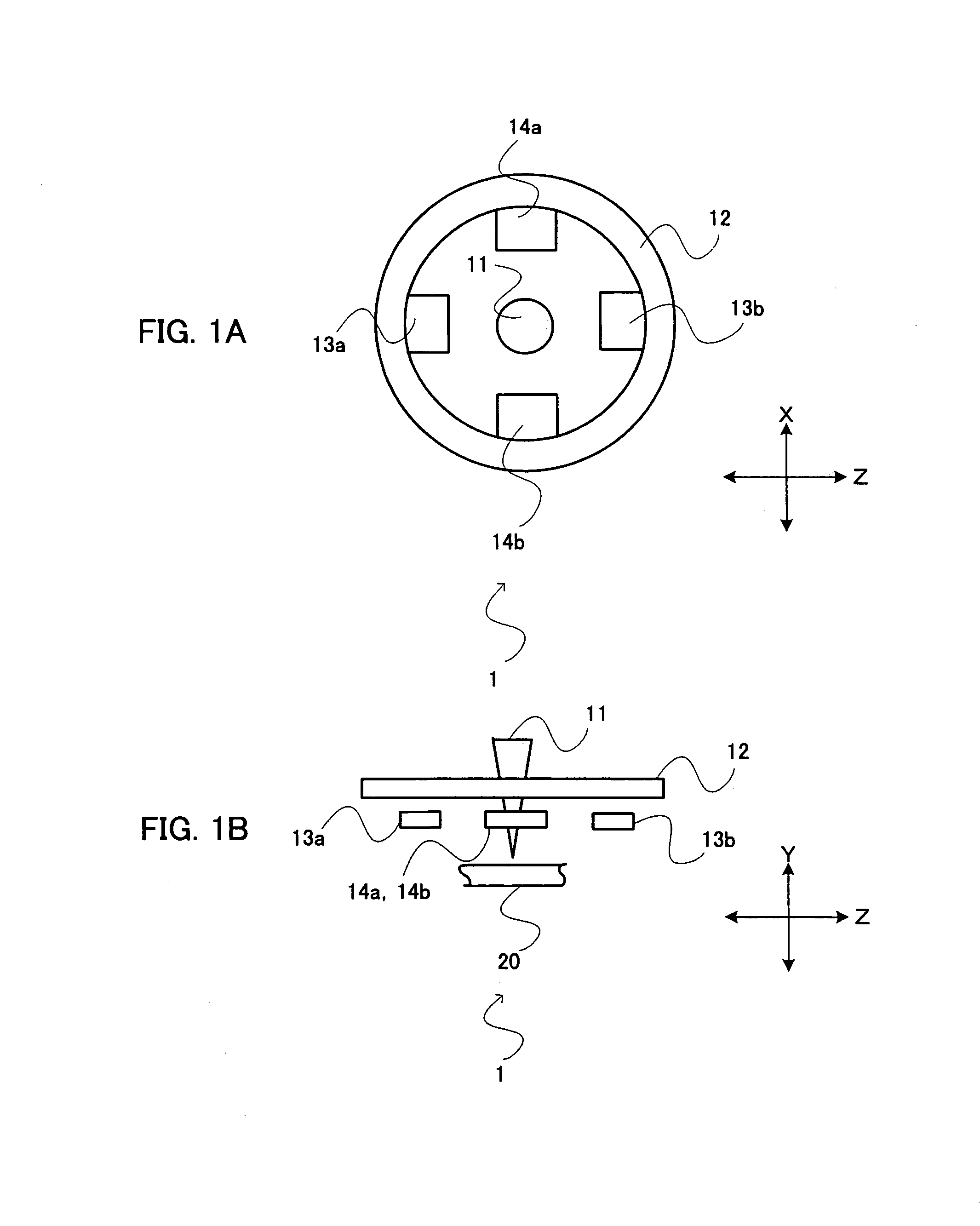
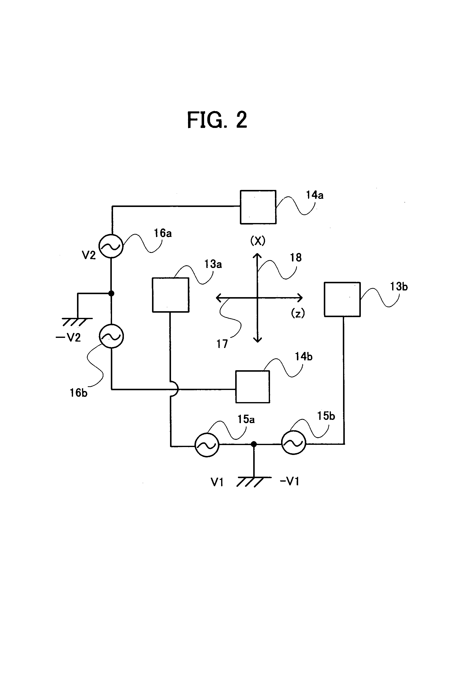
[0051]An embodiment of a dielectric recording / reproducing head associated with the present invention will be explained with FIG. 1A to FIG. 4. FIG. 1A is a plan view showing the embodiment of the dielectric recording / reproducing head. FIG. 1B is a side view of the embodiment of the dielectric recording / reproducing head. FIG. 2 is a schematic diagram showing a relationship between the placement of electrodes of the dielectric recording / reproducing head and application of voltages. FIG. 3 is a schematic diagram showing an operation of the dielectric recording / reproducing head. FIG. 4 is a schematic diagram to explain the recording / reproducing of information with respect to a ferroelectric substance.

[0052]As shown in FIG. 1A and FIG. 1B, a dielectric recording / reproducing head 1 associated with the embodiment is provided with: a probe 11 whose tip faces a ferroelectric recording medium 20 for applying an electric field to the ferro...


PUM

PropertyMeasurementUnit
angleaaaaaaaaaa
frequencyaaaaaaaaaa
frequencyaaaaaaaaaa

Abstract

A dielectric recording/reproducing head is provided with: a probe; a return electrode for returning a high-frequency component of an electric field applied from the probe; and bias electrodes, which are placed under the return electrode. By applying a voltage stronger than a coercive electric field between the probe and each of the bias electrodes, polarization domains are formed which have polarization directions parallel to a surface of a dielectric recording medium. The polarization directions are determined by selecting the bias electrode to which the voltage is applied, and four types of data are recorded on a predetermined site of the dielectric recording medium, which allows multivalued recording. Moreover, the polarization directions of the polarization domains are detected by an electric field which is formed by applying a voltage between the bias electrodes and which is parallel to the surface of the dielectric recording medium, causing data to be read out.

Description

BACKGROUND OF THE INVENTION[0001]1. Field of the Invention[0002]The present invention relates to a dielectric recording / reproducing head, a dielectric recording apparatus, a dielectric reproducing apparatus, and a dielectric recording / reproducing apparatus for recording information with multivalued data in microdomains of a dielectric substance or for reproducing it.[0003]2. Description of the Related Art[0004]As high-density, large-capacity recording / reproducing apparatuses of randomly accessible type, there are known an optical disk apparatus and a hard disk drive (HDD) apparatus. Moreover, a recording / reproducing technique using a scanning nonlinear dielectric microscopy (SNDM) for nanoscale analysis of a dielectric (ferroelectric) substance has been recently proposed by the inventors of the present invention.[0005]Optical recording uses an optical pickup with a laser as a light source. Data is recorded by forming pits that are concavo-convex on a disk surface or by forming the c...

Claims


Application Information

Patent Timeline
Patent Type & Authority Patents(United States)
IPC IPC(8): G11B9/00G11B9/02G11B9/14G11B11/08
CPCB82Y10/00G11B9/02G11B9/14G11B9/1409G11B11/08
Inventor CHO, YASUOONOE, ATSUSHI
Owner YASUO CHO
Why Eureka
Try Eureka