Time code signal transmitting method and time code signal transmitting apparatus

a time code signal and transmission method technology, applied in the field of time code signal transmission method and time code signal transmission apparatus, can solve the problems of deterioration in the precision of time code signal, error (change in data content) generation, and method or structure for detecting an error generated in time code signal not being carried out at all, so as to achieve high precision

Active Publication Date: 2006-12-19
PANASONIC CORP
View PDF2 Cites 16 Cited by
  • Summary
  • Abstract
  • Description
  • Claims
  • Application Information

AI Technical Summary

Benefits of technology

[0008]When the time code signal transmitting method or transmitting device is constructed in this way, an error generated on the time code signal at the time of regeneration, transmission or the like can be verified with high precision by comparing the receiving side checking data generated from the received time code signal to the transmitting side checking data read from the received time code signal.
[0009]Preferably, the present invention can be applied to a time code signal transmitting method or transmitting device for transmitting a single time code signal. Furthermore, the single time code signal is preferably an LTC signal. In this way, the present invention can be carried out in a system for transmitting a single time code signal. Therefore, an error can be verified without complicating a time code signal transmitting system.
[0010]It is preferable to use, as the check-receiving data, a data recorded on a user's bit area for the time code signal and to further attach the checking data to the user's bit area for the time code signal. In this way, an error can be verified in the user's bit area for the time code signal.
[0011]According to the present invention, an error of a time code signal (user's bit area) can be specified and detected in frames which constitutes picture signals. In a method and a device for transmitting a time code signal corresponding to a picture signal to which format conversion in which a change in the number of frames of picture signals per second is generated is applied, it is necessary that the position, on the signals, of the picture signal after the format conversion is specified in frames. Therefore, the present invention, which can detect an error in frames, is particularly effective for the case that such format conversion is performed.

Problems solved by technology

In a time code signal, an error (change in data content) may be generated by a reading failure or transmission failure when the time code signal is regenerated from a regenerating device or the signal is transmitted.
Such an error causes a deterioration in the precision of the time code signal.
Hitherto, however, the method or structure for detecting an error generated in time code signals has not been carried out at all, and effective proposals have not yet been made.

Method used


Image

  • Time code signal transmitting method and time code signal transmitting apparatus
  • Time code signal transmitting method and time code signal transmitting apparatus
  • Time code signal transmitting method and time code signal transmitting apparatus

Examples


Embodiment Construction

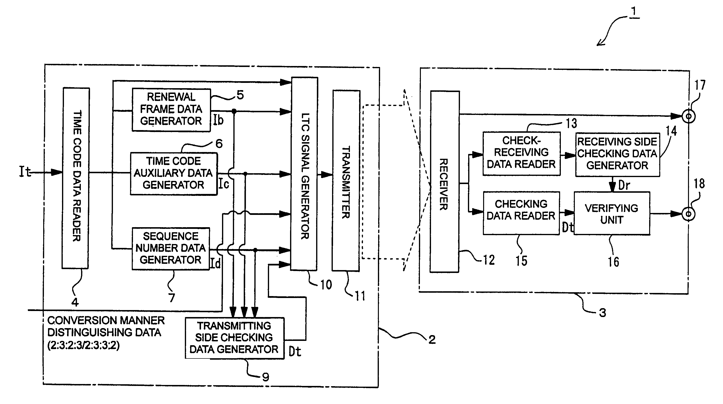
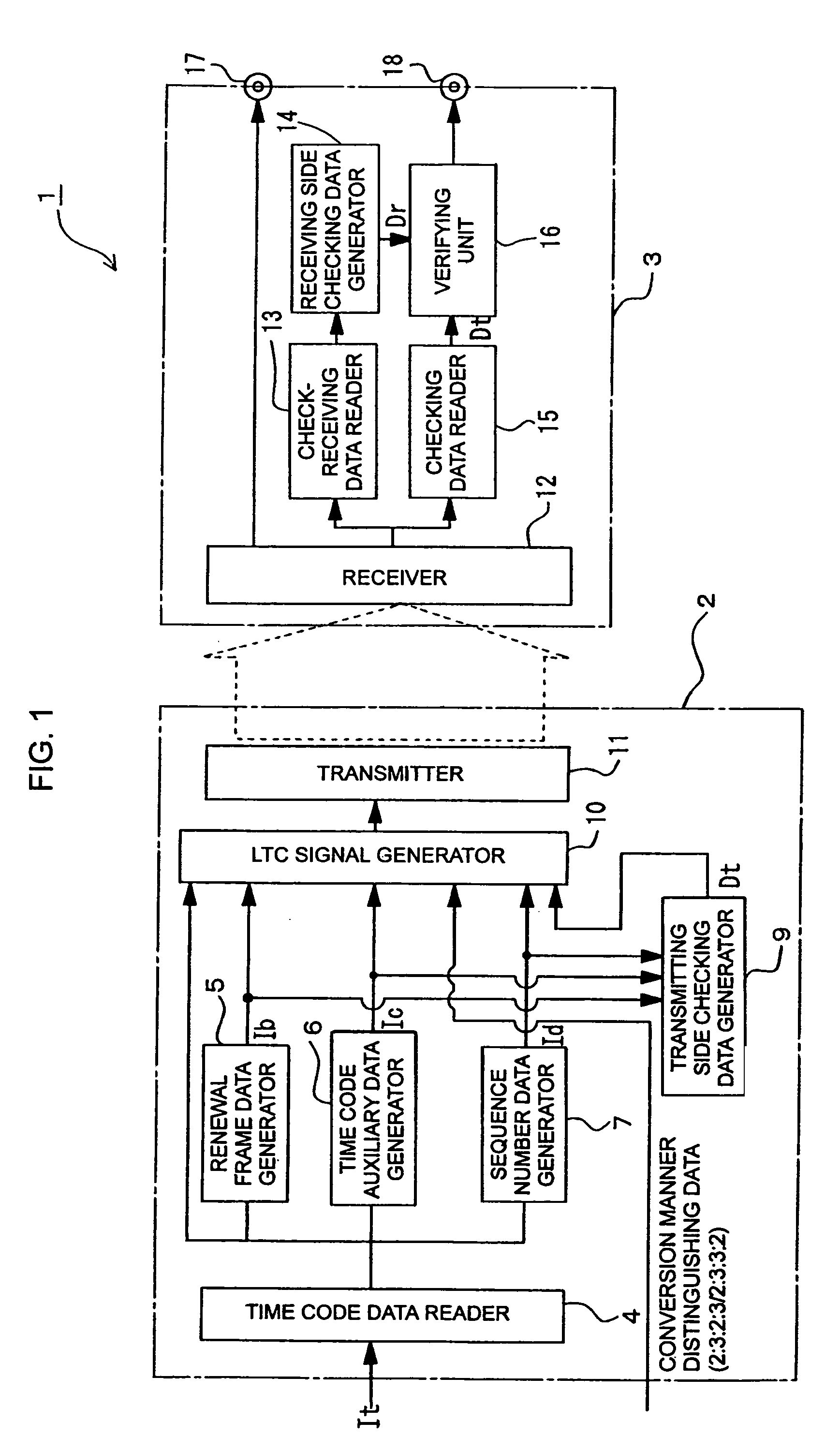
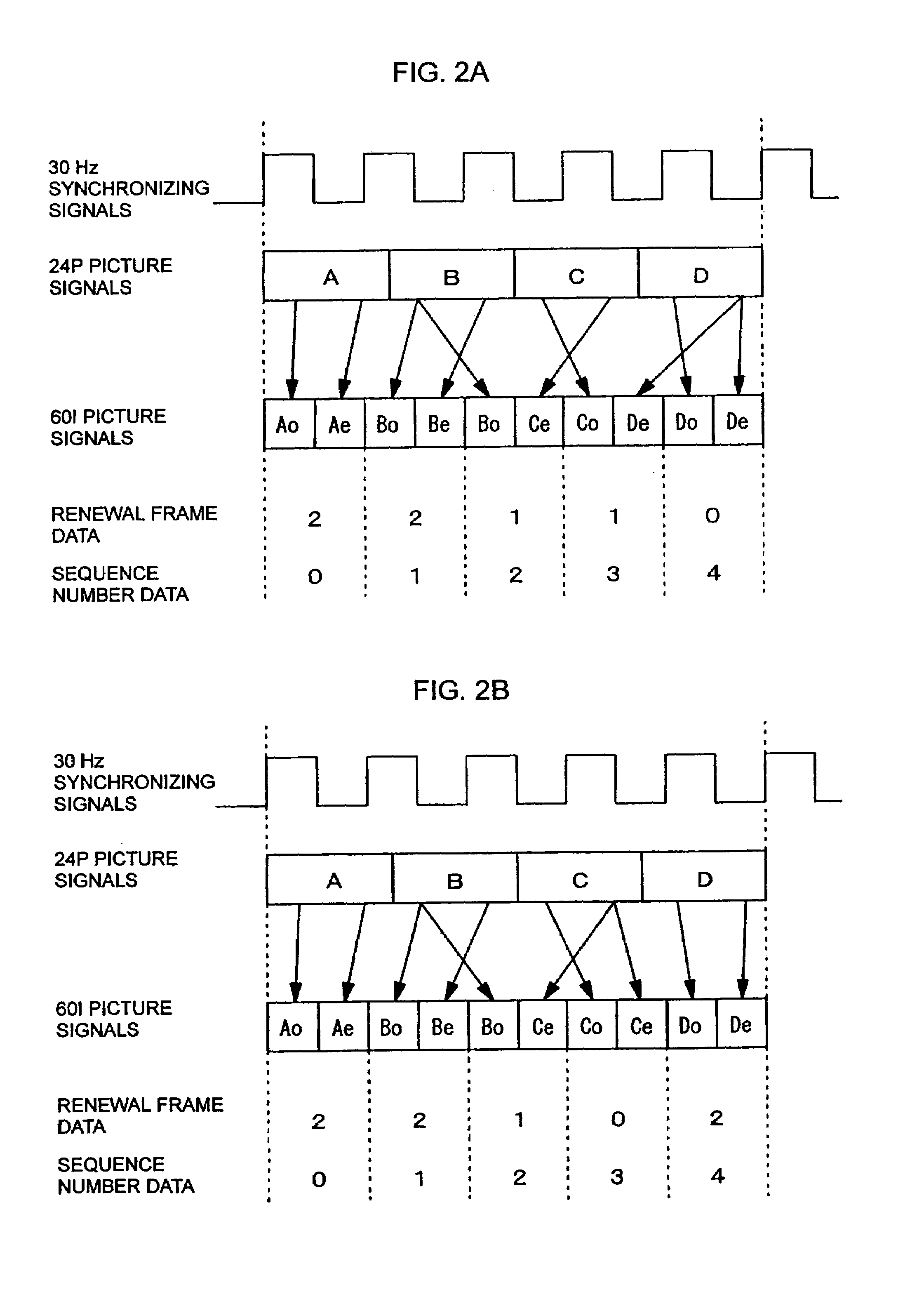
[0016]Referring to the drawings, the preferred embodiment of the present invention is described in detail hereinafter. FIG. 1 is a block diagram illustrating the structure of a time code signal transmitting device of the preferred embodiment of the present invention. In the present embodiment, it is assumed that format conversion is carried out. In the present embodiment, the present invention is carried out in the device for transmitting time code signals corresponding to picture signals after the format conversion. More specifically, in the present embodiment, it is assumed that a picture signal in a progressive format of 24 frames / second (hereinafter referred to as a 24P format) (hereinafter referred to as a 24P picture signal) is primarily converted to a picture signal in an interlace format of 30 frames / second (hereinafter referred to as a 60I format) (hereinafter referred to as a 60I picture signal).

[0017]In the present embodiment, the present invention is carried out in a tim...


PUM

PropertyMeasurementUnit
time code signal transmitting methodaaaaaaaaaa
timeaaaaaaaaaa
time codeaaaaaaaaaa

Abstract

The present invention comprises the step of reading a check-receiving data included in a transmitted time code signal and using the read check-receiving data to generate a transmitting side checking data, and the step of attaching the transmitting side checking data to the transmitted time code signal, as a pre-processing step at the time of transmitting the time code signal. The present invention comprises the step of reading the check-receiving data from the received time code signal and using the read check-receiving data to generate a receiving side checking data, and the step of reading the transmitting side checking data from the received time code signal and comparing the read transmitting side checking data to the receiving side checking data, thereby verifying whether or not an error is generated in the received time code signal. In this way, an error can be detected in the time code signal, as a post-processing step after the time code signal is received.

Description

TECHNICAL FIELD[0001]The present invention relates to a method and a device for transmitting a time code signal generated to be attached to a picture signal.BACKGROUND ART[0002]As a time code signal used in the transmission of a picture signal, there is an LTC (linear time code) signal, which is recorded on a voice frequency band after being subjected to bi-phase mark modulation. Time code signals are transmitted in synchronization with picture signals.[0003]In a time code signal, an error (change in data content) may be generated by a reading failure or transmission failure when the time code signal is regenerated from a regenerating device or the signal is transmitted. Such an error causes a deterioration in the precision of the time code signal. For this reason, it is necessary to detect the generation of the error in the time code signal with high accuracy. When the error can be detected, the use of the time code signal can be stopped. The location of the error can also be resto...

Claims


Application Information

Patent Timeline
Patent Type & Authority Patents(United States)
IPC IPC(8): H04L27/04G06F11/10H04N11/02H03C1/52H04N5/76G11B27/034G11B27/28
CPCG11B27/034G11B27/28H04N9/8205
Inventor HOSODA, TAKAHARUURO, KATSUJISHIMAMURA, YUKIOUENO, MASAJI
Owner PANASONIC CORP
Why Eureka
Try Eureka