[0004]An object of the present invention is to achieve a method that makes an installation of a stator winding possible with no or only few cable joints, and which furthermore reduces the risk of the winding cable being subjected to damages during the installation work.SUMMARY OF THE INVENTION
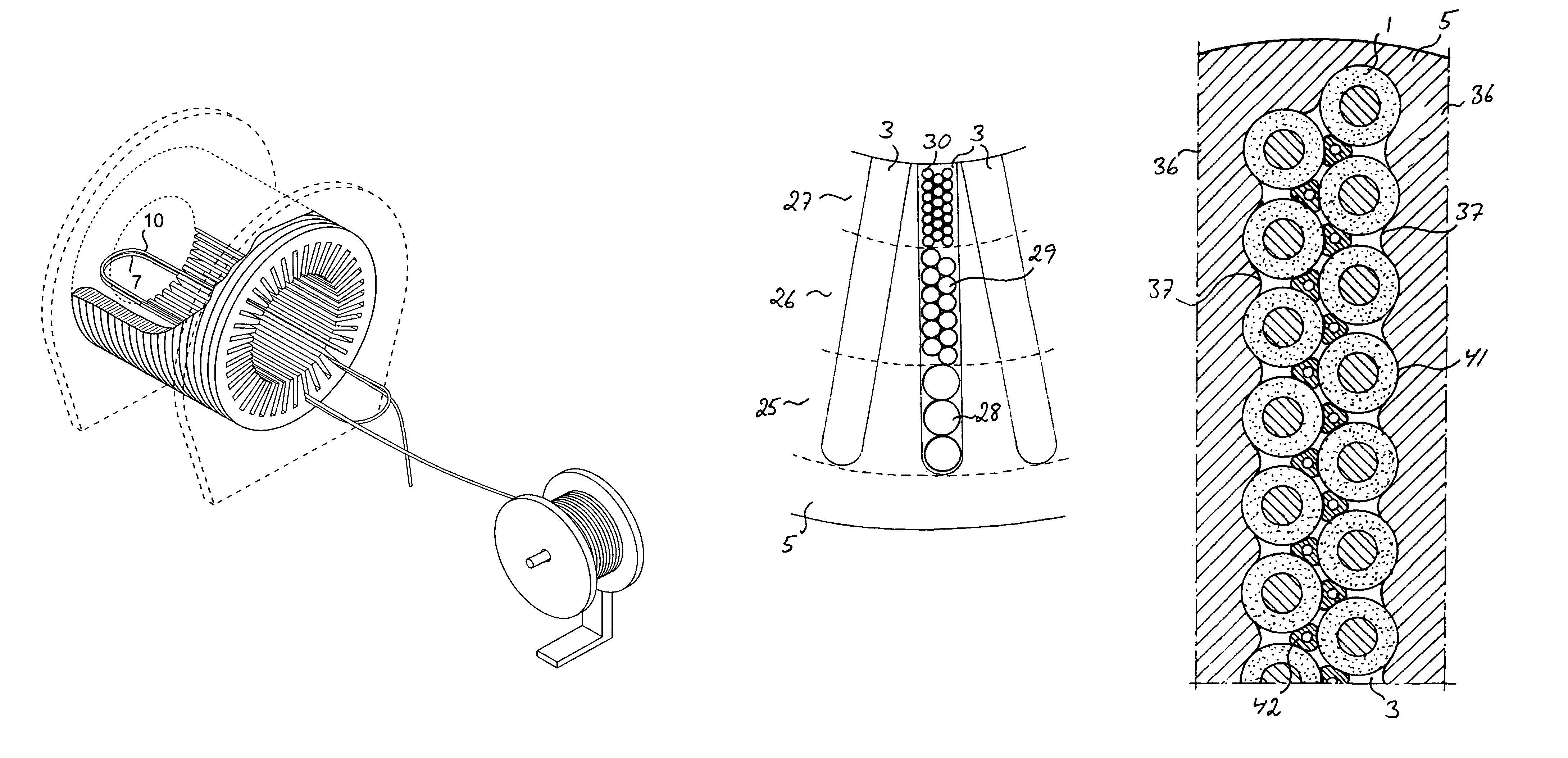
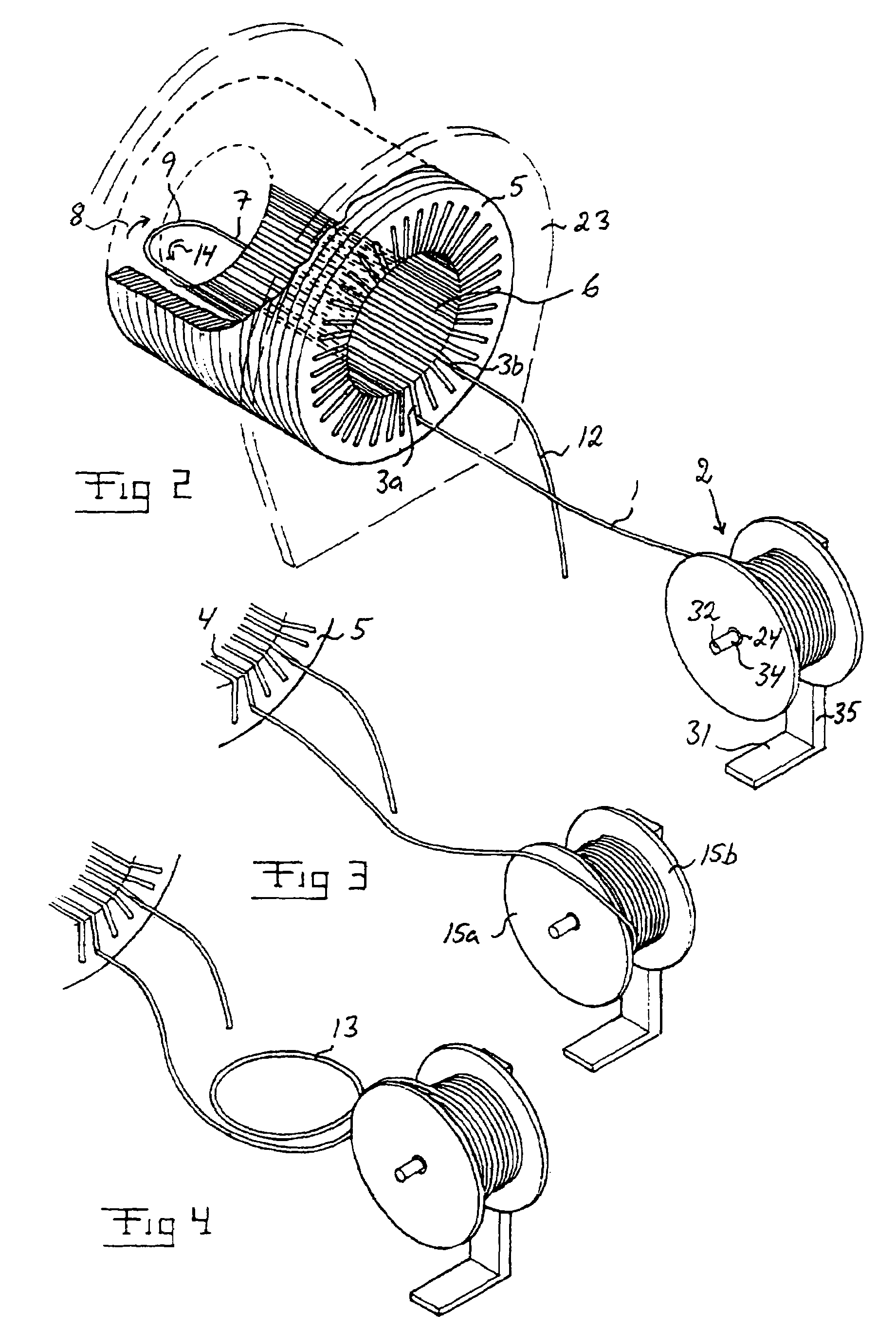
[0005]The inventional solution implies that it will be possible with reasonable working efforts to, if so desired, install a complete stator winding without any cable joints even in very large stator cores. Since the winding cable, with the inventional method, does not have to be threaded, i.e. axially drawn or pushed, through the winding slots, the risk of cable damages are furthermore considerably reduced as compared to the previously used method of installation. By lifting off a turn of a cable from the cable reel over one or the other of the gables of the cable reel, depending on the winding direction of the winding turn that is in turn to be installed in the intended winding slots, twistings of the cable resulting in kink are avoided. This way of lifting off a cable turn from the cable reel can be compared to the “lifting over” of the cable turn from the cable reel to the stator core. Without proceeding in this particular manner, the cable would very rapidly be twisted so much that it would be unwieldy and impossible to wind in the desired winding pattern.
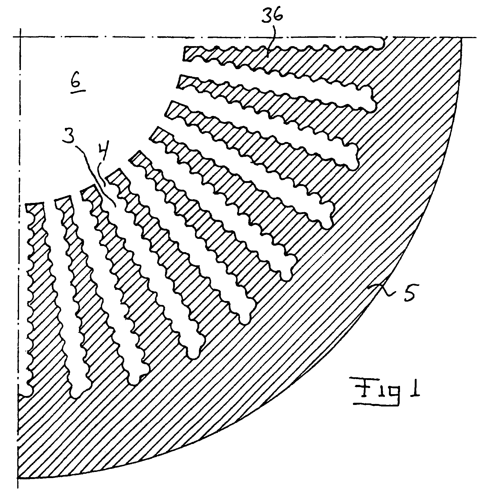
[0009]According to a further preferred embodiment of the invention, the stator winding is installed, as seen in a cross-section through the stator core, in two or several radially successive ring-shaped areas, where the respective area has a radial extension along the winding slots and covers a complete turn around the stator core, the different areas being successively filled with cable sections in such a way that a radially outer section is filled the whole turn around with all the cable sections intended to be included in this area before an area located radially inside the outer area is filled with cable sections. In this way, it will be easy to get a good structure on the construction of the stator winding. The transition from one area to the next area will for instance offer suitable and natural places for any possibly required cable joints, for instance between cables of different thickness.
[0010]According to a further preferred embodiment of the invention, a band-shaped element, preferably of the same material as the outer layer of the cable, is placed between the cable and the walls of the respective winding slot at the areas of the axial ends of the winding slot where the cable exits the winding slot. Hereby, the outer layer of the cable is protected in the sensitive area where the cable exits the winding slot. Without such a protective element, there is a risk of wear between the cable and the stator core, which could result in serious damages on the outer layer of the cable. By letting the protective element consist of the same material as the outer layer of the cable, it is furthermore secured that the protective element does not subject the sensitive outer layer of the cable to any unsuitable substances, which for instance could effect the electric and magnetic properties of the outer layer, at a later wear between the protective element and said outer layer.
[0011]According to a further preferred embodiment of the invention, a cable section is put in place in the intended winding slot with the aid of a rod-shaped element having essentially the same external
diameter as the next cable section that is intended subsequently to be placed immediately outside said cable section, which rod-shaped element is placed against the cable section along the cable section after the cable section has been inserted into the winding slot, whereupon said element is acted upon by impacts so that the element is made to occupy the place in the winding slot intended for the next cable section, whereby the element is made to press the cable section down into its intended place in the winding slot. In this way, it will be possible to force a cable section to occupy the intended position in the winding slot without subjecting the sensitive cable for any direct action by a striking tool. Owing to that the rod-shaped element has essentially the same external
diameter as the next cable section that is intended to be placed immediately outside the cable section in question, it is furthermore secured that the cable section, when being installed with the aid of said element, will occupy exactly the correct position, since the element completely will occupy the place intended for the next cable section.

