Method and apparatus for deploying a line in coiled tubing

a technology of coiled tubing and installation method, which is applied in the direction of cables, instruments, and cables, etc., can solve the problems of unfavorable operation, unrealistically high cost of such a system, and development of pressured systems, so as to avoid friction forces and ejection pressures

Inactive Publication Date: 2006-12-26
SCHLUMBERGER TECH CORP
View PDF13 Cites 48 Cited by
  • Summary
  • Abstract
  • Description
  • Claims
  • Application Information

AI Technical Summary

Benefits of technology

[0018]The present invention provides methods and apparatus for deploying a line in coiled tubing that are suitable for use when the coiled tubing is spooled on a reel or deployed in a borehole and when under well pressure. A line reel assembly is provided wherein the line is disposed on a reel within a pressure housing. The line is deployed via a deployment tube that can be hermitically connected to the coiled tubing. When the deployment tube is connected to the coiled tubing before deployment, the line reel assembly is pressured as the coiled tubing is pressured upon injection into the wellbore. In this manner, the present invention avoids the friction forces and ejection pressures encountered when attempting to insert a cable at ambient pressure into coiled tubing at well pressure. The line is propelled through the deployment tube into the coiled tubing by fluid flow diverted to the deployment tube via an inlet port from the pumped fluid passing through the coiled tubing. In this way, the line is conveyed by fluid flow without mechanical efforts. This makes the present invention particularly applicable for providing a line that comprises fiber optics.

Problems solved by technology

It is apparent that the additional time and effort required to place cable in coiled tubing in these manners is operationally undesirable.
It discards the concept, however, noting problems with aligning cable with coiled tubing and controlling the cable insertion are expected, along with an unrealistically high cost for such a system.
These impediments among others have prevented development of a pressured system for injection of cable into coiled tubing.
The forces applied to the cable are low so the potential for damaging the cable during installation is less than when using a mechanical pulling device.
Several difficulties remain when providing wireline cable in coiled tubing.
For example, managing slack in the wireline while it is interior to the coiled tubing poses operational difficulties.
In addition, the presence of wireline in the coiled tubing reduces the available capacity for pumped fluids within the coiled tubing.
Disadvantages of this method include the need for providing a separate conduit for single optical fiber installation.
Furthermore, the requirement of this configuration that a conduit is provided in the initial installation limits operational flexibility; this limitation is addressed by the present invention.

Method used


Image

  • Method and apparatus for deploying a line in coiled tubing
  • Method and apparatus for deploying a line in coiled tubing
  • Method and apparatus for deploying a line in coiled tubing

Examples


Embodiment Construction

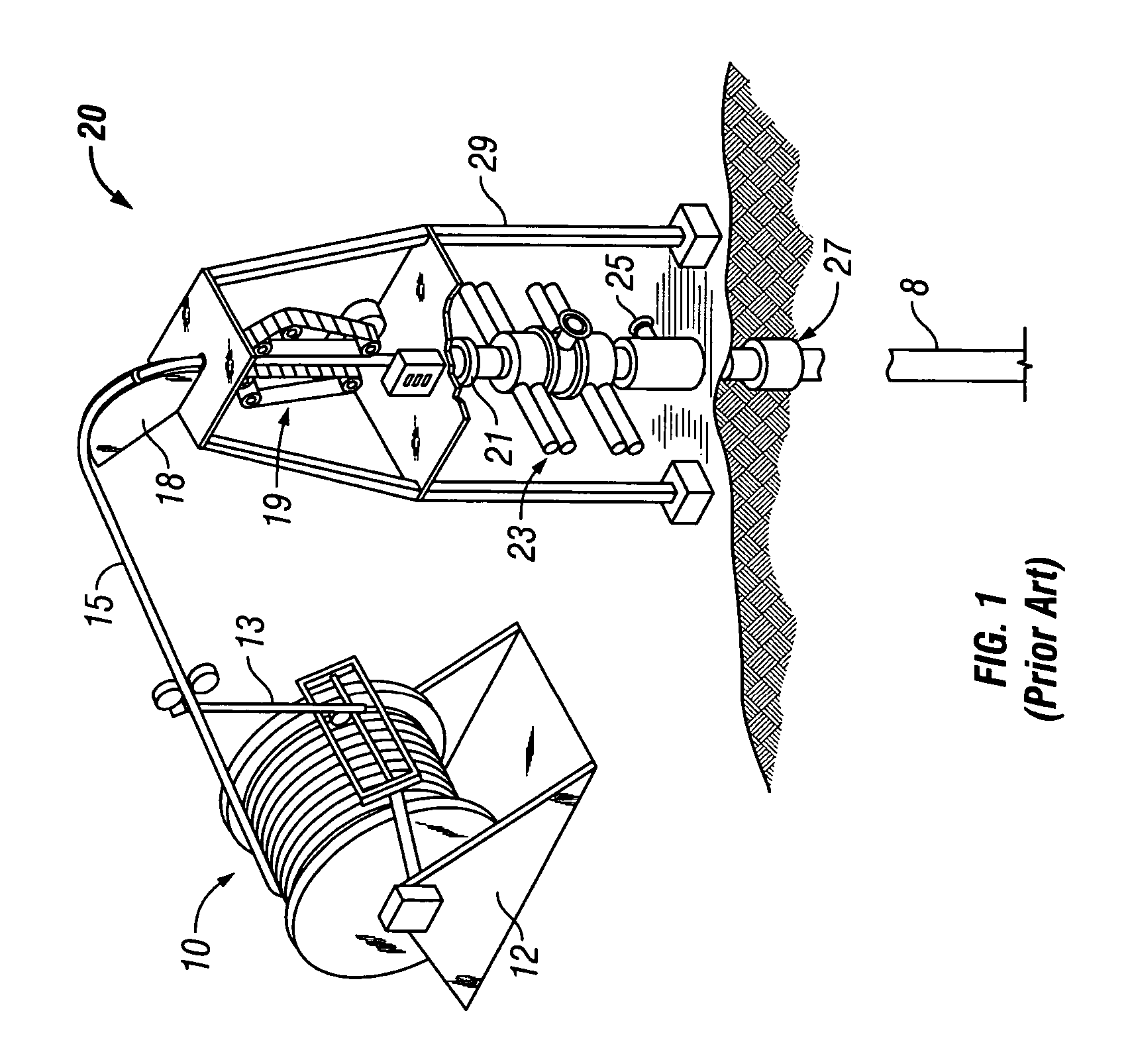
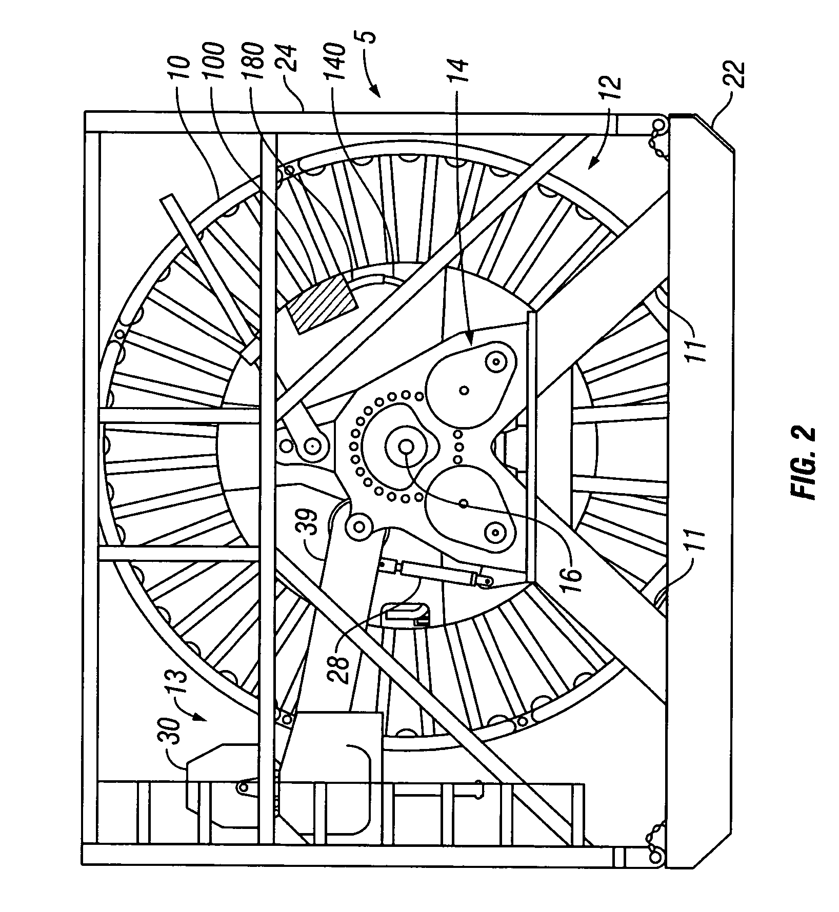
[0032]Referring to the drawings in detail, wherein like numerals denote identical elements throughout the several views, there is shown in FIG. 2 a coiled tubing reel assembly 5 shown generally as a coiled tubing reel 10 on a reel stand 12 placed on a skid 22. While the reel assembly is shown on a skid in FIG. 2, it similarly could be placed on a trailer, mounted on a truck, or provided in a variety of configurations for transport and use, to which the present invention is similarly applicable. The reel 10 is shown mounted on an axle 16 and supported by legs 11. Drive unit 14 is powered by one or more motors and is used provide rotational power to spool and unspool coiled tubing 15 on reel 10. When deploying coiled tubing 15 in a wellbore 8, the coiled tubing reel 10 is rotated by the drive unit 14 to unspool the coiled tubing 15 which fed from the reel 10 through the levelwind assembly to the injector system 20 for injection under pressure into the wellbore. A hydraulic connection ...


PUM


Abstract

Methods and apparatus for deploying a line in a borehole using coiled tubing are presented. Methods are applicable for use in deploying a line in a coiled tubing when the coiled tubing is spooled on a reel or deployed in a wellbore. A line reel provided in a pressure housing is used to supply a line for deployment using fluid flow in coiled tubing. The line reel assembly and deployments methods are suitable for use under well pressure. The line may comprise fiber optics. Subsequent to deployment of coiled tubing with a line dispose therein, the coiled tubing may be withdrawn, leaving the line in the wellbore.

Description

[0001]This patent application is a non-provisional of provisional application Ser. No. 60 / 480,347 filed Jun. 20, 2003.BACKGROUND OF THE INVENTION[0002]1. Field of the Invention[0003]The present invention relates generally to installing a line in coiled tubing and more particularly to methods and apparatus for deploying fiber optics under pressure into a wellbore using coiled tubing.[0004]2. Description of the Related Art[0005]Coiled tubing is used frequently in various borehole applications. A typical configuration for the surface handling equipment for coiled tubing is shown generally in FIG. 1. The surface handling equipment includes an injector system 20 on injector supports 29 and coiled tubing reel assembly 10 on reel stand 12. The tubing is deployed into or pulled out of the well using an injector head 19. The equipment further includes a levelwind mechanism 13 for guiding coiled tubing 15 on and off the reel 10. The tubing 15 passes over tubing guide arch 18 which provides a ...

Claims


Application Information

Patent Timeline
Patent Type & Authority Patents(United States)
IPC IPC(8): E21B19/22E21B17/20E21B23/08G02B6/44H02G1/08H02G11/02
CPCE21B17/206E21B23/08G02B6/4464H02G1/086H02G11/02G02B6/52E21B17/20G02B6/44G02B6/4401H02G1/08
Inventor ADNAN, SARMADGAY, MICHAEL G.
Owner SCHLUMBERGER TECH CORP
Why Eureka
Try Eureka