Vehicle driving force control apparatus and method

a technology for driving force control and vehicle, which is applied in the direction of process and machine control, instruments, tractors, etc., can solve the problems of reducing deteriorating the fuel economy of the vehicle, and reducing the overall so as to achieve the effect of lowering the total energy efficiency of the vehicl

Inactive Publication Date: 2006-12-26
NISSAN MOTOR CO LTD
View PDF14 Cites 15 Cited by
  • Summary
  • Abstract
  • Description
  • Claims
  • Application Information

AI Technical Summary

Benefits of technology

[0003]The starting acceleration performance of the above-proposed vehicle under low-friction road conditions becomes increased as the starting torque of the motor increases with the amount of electricity produced by the generator. However, each of the motor and the generator generally operates with about 60 to 90% efficiency. There thus arises an energy loss during the conversion of engine mechanical energy into electric energy by the generator and the conversion of the electric energy into mechanical energy by the motor. The total energy efficiency of the vehicle is lowered due to such an energy loss, thereby causing deteriorations in the fuel economy of the vehicle as well as the acceleration performance of the vehicle under high-friction road conditions.
[0005]It is therefore an object of the present invention to provide a driving force control apparatus for an automotive vehicle, capable of reducing an energy loss while securing a certain level of acceleration performance at a start of the vehicle.

Problems solved by technology

There thus arises an energy loss during the conversion of engine mechanical energy into electric energy by the generator and the conversion of the electric energy into mechanical energy by the motor.
The total energy efficiency of the vehicle is lowered due to such an energy loss, thereby causing deteriorations in the fuel economy of the vehicle as well as the acceleration performance of the vehicle under high-friction road conditions.

Method used


Image

  • Vehicle driving force control apparatus and method
  • Vehicle driving force control apparatus and method
  • Vehicle driving force control apparatus and method

Examples


Embodiment Construction

[0020]The invention will be described below with reference to the drawings.

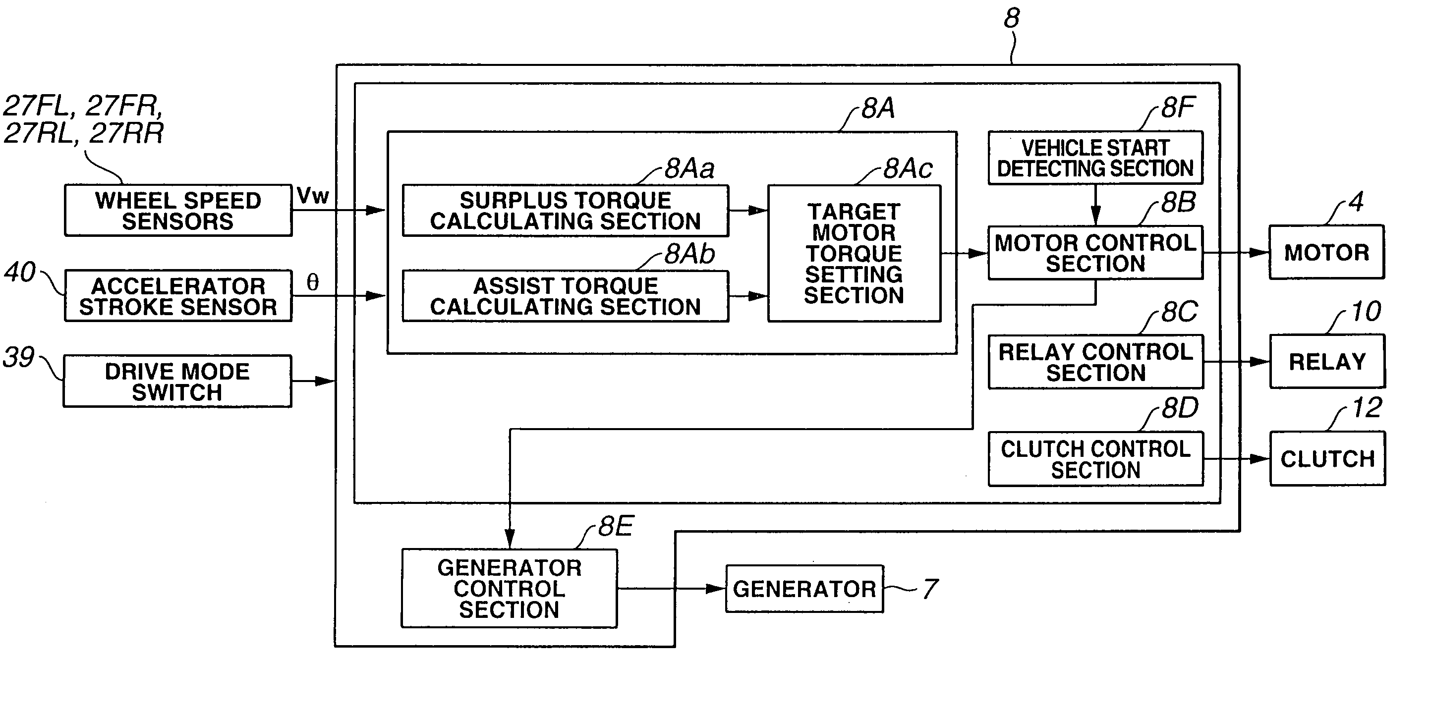
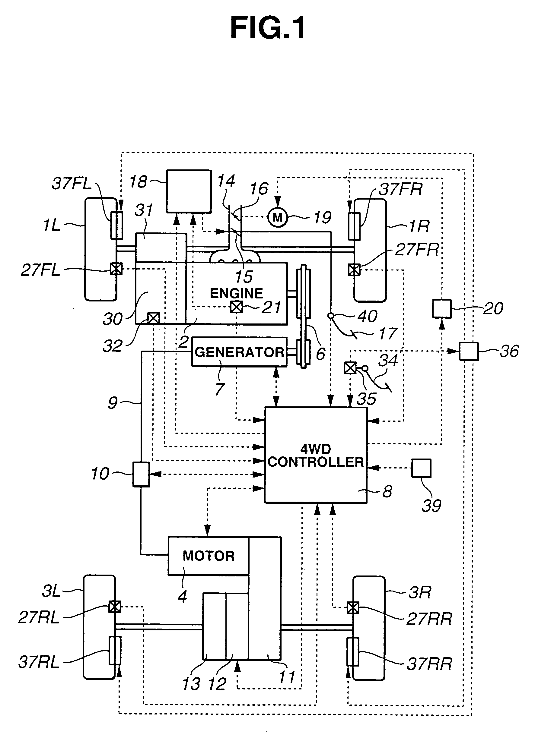
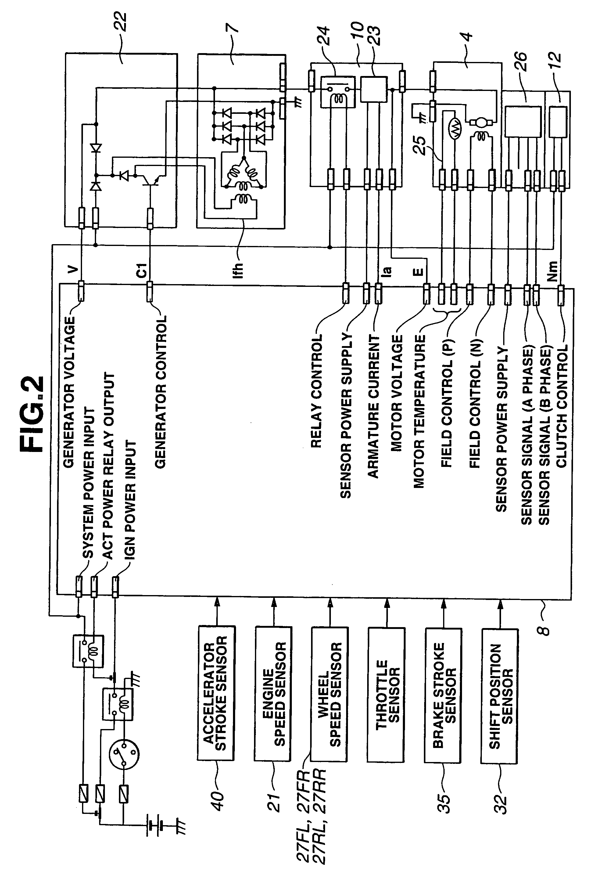
[0021]As shown in FIGS. 1 and 2, there is provided a vehicle with a driving force control apparatus including engine 2, transmission 30, electric motor 4, electric generator 7, a brake with brake pedal 34 and braking units 37FL, 37FR, 37RL and 37RR, drive mode switch 39 and various control modules such as engine controller 18, a transmission controller, motor controller 20, brake controller 36 and 4WD controller 8 according to one embodiment of the present invention. It should be noted that the vehicle of the present embodiment is designed as a four-wheel drive vehicle having front left and right wheels 1L and 1R as main drive wheels rotated by the driving force from engine 2, rear left and right wheels 3L and 3R as subsidiary drive wheels rotated by the driving force from motor 4 and accelerator pedal 17 as an acceleration indication unit (or accelerator opening indication unit) operated by a vehicle driver....


PUM


Abstract

There is provided a driving force control apparatus for an automotive vehicle, including an internal combustion engine to rotate main drive wheels of the vehicle by engine torque, a generator driven by the engine; a motor powered by the generator to rotate subsidiary drive wheels of the vehicle by motor torque in a four-wheel drive state, a detecting section to detect a vehicle start failure under which the vehicle has failed to make a start in response to a vehicle starting operation in the four-wheel drive state, and a motor torque characteristic changing section to change a target torque characteristic of the motor to a higher level so as to increase the motor torque upon detection of the vehicle start failure.

Description

BACKGROUND OF THE INVENTION[0001]The present invention relates an apparatus and method for controlling the driving force of an automotive vehicle to achieve a four-wheel drive state.[0002]Japanese Laid-Open Patent Publication No. 2000-318473 proposes one type of four-wheel drive vehicle, which has an engine drivingly connected to main drive wheels of the vehicle, a motor drivingly connected to subsidiary drive wheels of the vehicle and a generator driven by the engine to supply power to the motor so as to achieve a four-wheel drive state of the vehicle. In this proposed structure, the vehicle does not necessarily require a battery as a power source of the motor.SUMMARY OF THE INVENTION[0003]The starting acceleration performance of the above-proposed vehicle under low-friction road conditions becomes increased as the starting torque of the motor increases with the amount of electricity produced by the generator. However, each of the motor and the generator generally operates with abo...

Claims


Application Information

Patent Timeline
Patent Type & Authority Patents(United States)
IPC IPC(8): B60K6/04B60K6/44B60W20/00B60K6/52B60K6/54B60K17/356B60L50/16B60W10/08
CPCB60K6/44B60K6/52B60W10/08B60K17/356B60L2240/423B60W2520/26B60W2540/10B60W2540/103B60W2710/083Y02T10/623Y02T10/6265Y02T10/642Y02T10/62Y02T10/64
Inventor MATSUDA, TOSHIRO
Owner NISSAN MOTOR CO LTD
Why Eureka
Try Eureka