Method and device for simultaneous production of energy in the forms electricity, heat and hydrogen gas

a technology of electricity and hydrogen gas, which is applied in the direction of gasification process details, fuel cells, petrochemical industry, etc., can solve the problems of energy intensive, strong impact on the environment, and the recovery and upgrading of extra heavy oil and bitumen, and achieve energy efficient effects

Active Publication Date: 2012-10-25
ZEG POWER
View PDF6 Cites 7 Cited by
  • Summary
  • Abstract
  • Description
  • Claims
  • Application Information

AI Technical Summary

Benefits of technology

[0069]The bio-methane (from the biogas) may be used for hydrogen production. If, however, the CO2 is separated from the biogas for production of vehicle grade methane, this methane would most likely be used directly in the transport sector. Fuel or syngas for the energy hydrogen production plant would be made from suitable biomass. Again, all the bio CO2 is captured, giving double “bonus” if used or stored. And again, the individual processes on the left hand side of the drawing are not explained to any detail here, since they as such are not part of the present invention. The interesting part in the present context is the ability of the method according to the present invention to adapt to such complex systems of energy demanding process units, providing sustainable deli

Problems solved by technology

One of the major challenges in this connection is the recovery and upgrading of extra heavy oil and bitumen.
The recovery and upgrading of these resources, for example from tar-sands, are very energy intensive processes with strong impact on the environment.
However, use of natural gas and/or syngas results in release of substantial amounts of CO2 into the atmosphere, contributing to global warming.
If CO2-capture, in such cases, is based on to-d

Method used


Image

  • Method and device for simultaneous production of energy in the forms electricity, heat and hydrogen gas
  • Method and device for simultaneous production of energy in the forms electricity, heat and hydrogen gas
  • Method and device for simultaneous production of energy in the forms electricity, heat and hydrogen gas

Examples


Embodiment Construction

[0082]The following table illustrates the versatility of the present method, by showing

Fraction to H2FuelEnergy producedgas formingutilisation(relative amounts)reactorin fuel cellCell voltageElectricityH2Heat0.10.450.624%13%63%0.10.70.6540%13%470.10.90.8567%13%200.260.450.620%33%47%0.260.70.6533%33%34%0.260.90.8555%33%12%0.50.450.613%63%24%0.50.90.731%63%0%0.70.60.68%89%4%0.70.60.611%89%0%

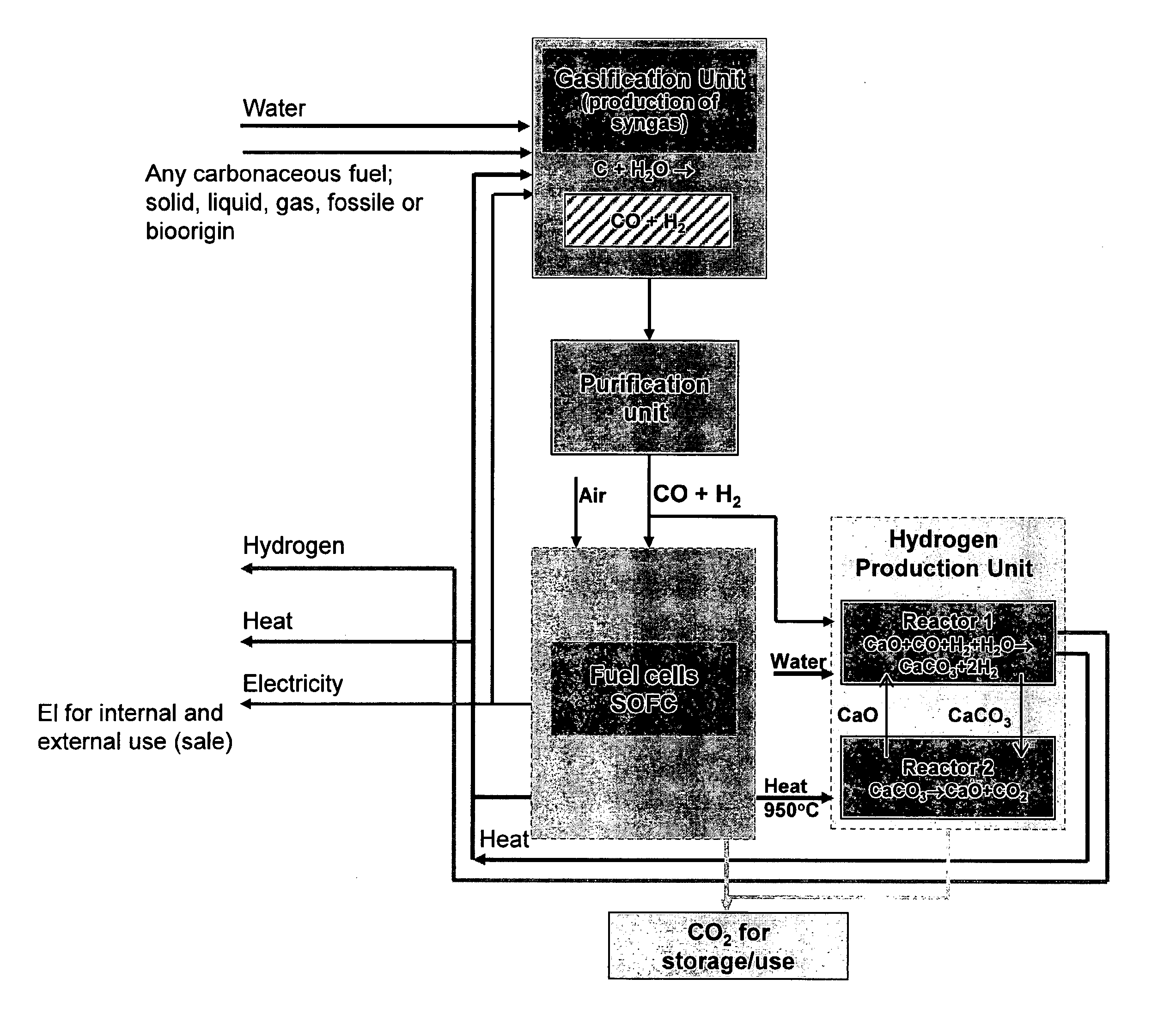
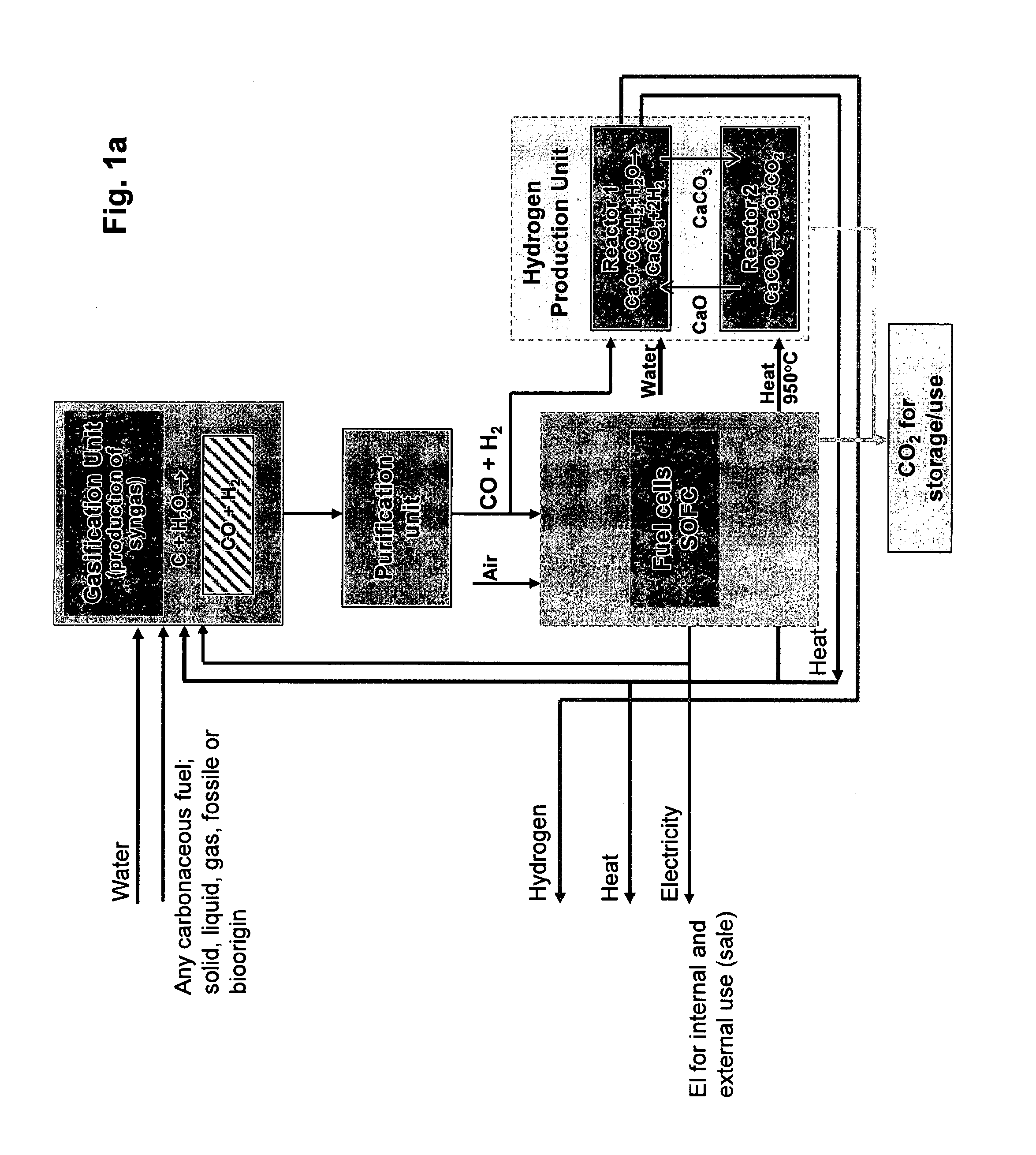
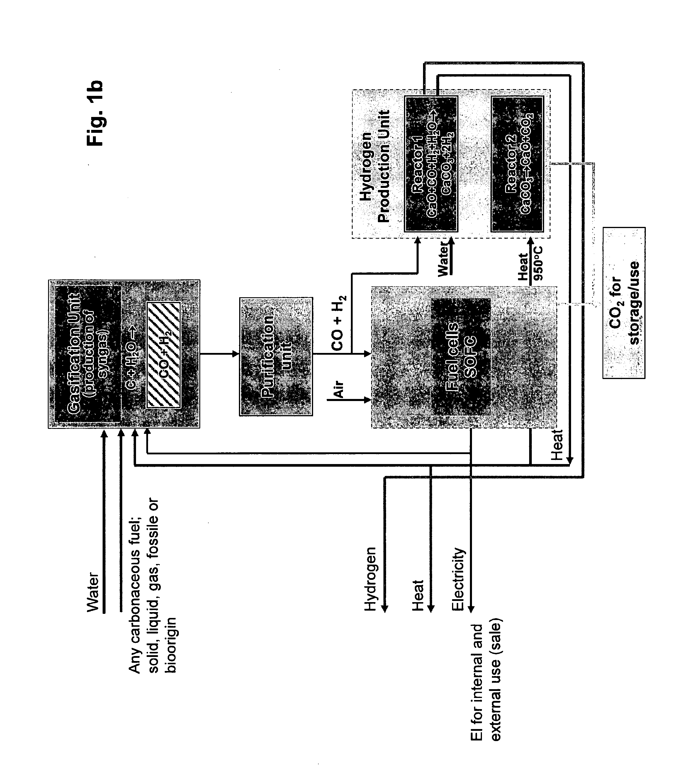
[0083]The calculations are based on syngas produced by reacting carbon with water:

C+H2O═>CO+H2

[0084]The electricity production is given by:

Electricity production=4*F*Cell Voltage*Fuel Utilisation in fuel cell*(1−Split)

where F=Faradays constant.

and Split=Fraction to H2 gas forming reactor

[0085]The hydrogen production is given by:

Hydrogen production=Split*2*dH_H2

where dH_H2=heating value of H2.

[0086]The net heat production is given by:

Heat=dH_C−Electricity production−hydrogen production

where dH_C is the heating value of carbon.

[0087]The examples above illustrate the versatility of the device accord...


PUM


Abstract

A method and device for sustainable, simultaneous production of energy in the forms electricity, hydrogen gas and heat from a carbonaceous gas, the method having the following steps: 1. continuously dividing a feed charge of carbonaceous gas into a first feed gas flow and a second feed gas flow, 2. charging the first feed gas flow to a primary SOFC to produce electricity and heat and CO2, 3. charging the other feed gas flow, to a hydrogen gas forming reactor system to produce hydrogen and CO2, 4. heating the hydrogen gas forming system at least partially by heat developed in at least one SOFC, 5. optionally capturing the CO2 formed in the primary SOFC by burning the “afterburner” gases in pure oxygen and drying the exhaust gas, 6. capturing the CO2 formed in the hydrogen gas forming reactor system by use of an absorbent.

Description

[0001]The present invention relates to a method and a device for simultaneous production of energy in the forms electricity, heat, and hydrogen gas, based on syngas and / or natural gas, which in turn may be derived from a number of primary energy sources.BACKGROUND[0002]The worlds demand for electric power, heat and hydrogen will in the foreseeable future be based on gaseous, liquid or solid fossil fuels. Thus international concerns over global warming would be increasingly focusing on carbon capture and storage (CCS). Development of environmentally friendly, cost and energy efficient technologies, including handling of the CCS-issue, is therefore inevitable.[0003]One of the major challenges in this connection is the recovery and upgrading of extra heavy oil and bitumen. Because of a simultaneous global increase in the fossil energy demand and decrease in the conventional resources, the oil industry will turn to unconventional resources. It should in this connection be mentioned that...

Claims


Application Information

Patent Timeline
IPC IPC(8): H01M8/06
CPCB01D53/62Y02E50/18C01B3/48C01B2203/0233C01B2203/0283C01B2203/066C01B2203/84C01B2203/86H01M8/04007H01M8/0612H01M8/0662H01M8/0668H01M16/003Y02C10/04Y02E60/50C10G2300/1011C10J3/00C10J2300/0916C10J2300/0943C10J2300/1612C10J2300/1646C10J2300/1665C10J2300/1681C01B3/34Y02P20/145Y02P30/20C01B3/56C01B2203/0216C01B2203/042C01B2203/0425C01B2203/0475C01B2203/0833C01B2203/1241Y02C20/40Y02E50/10Y02P20/129Y02P30/00Y02P20/151
Inventor RAAHEIM, ARNEVIK, ARILD
Owner ZEG POWER
Why Eureka
Try Eureka