Time-Locked Data Alignment in Distributed Embedded Systems

a distributed control system and embedded system technology, applied in the field of instrumentation and control, can solve the problems of limiting the amount of renewable energy that can be used, the uncertainty of the phase the difficulty of adjacent power converters to correctly track the phase angle and frequency of the grid, so as to facilitate all of the controlled power delivery devices, improve the electrical grid, and regulate the effect of voltage stabilization

Active Publication Date: 2018-03-29
NATIONAL INSTRUMENTS
View PDF2 Cites 9 Cited by
  • Summary
  • Abstract
  • Description
  • Claims
  • Application Information

AI Technical Summary

Benefits of technology

[0014]Various embodiments disclosed herein provide a new way of time synchronizing the control operation of distributed control systems / embedded systems, e.g. inverters or power delivery devices or embedded systems included in the power delivery devices, which allows the coordination of the control of the distributed systems power delivery devices, eliminating any contention between the devices and the devices attempting to “compete” or “fight” with each other. Various embodiments of control technologies described herein facilitate the addition of increasing numbers of power electronics power delivery devices to the grid (power delivery system) causing the system to actually become increasingly more resilient, robust and stable, as opposed to more and more unreliable and less stable as more power converted control systems are added. Rather than detracting from stability and power quality, power electronics converters (or power electronics power delivery devices) can thereby play a significant role in the improvement of the electrical grid. The coordination of the power delivery devices may include aligning the phase angle between any or all of the power delivery devices tied to the grid, via TSN, which is more accurate than phase locking to the measured grid voltages. This facilitates all of the controlled power delivery devices (e.g. inverters) tied to the power grid being able to share and agree upon the phase angle over their respective TSN connections. In this manner, each power delivery device (e.g. inverter) may assist in regulating and stabilizing the voltage and frequency of the power grid. Consequently, as more energy sources that use power electronics inverters to deliver their power onto the grid are added, the stability and robustness of the grid actually increases rather than decreases. Furthermore, the real-time communication links between the power delivery devices (e.g. inverters) may be used to balance the supply and the demand of energy as required, even over long distances. This makes it possible to easily provide 100% of the delivered power from renewable sources, as these new sources of energy stabilize rather than destabilize the power grid, while also balancing supply and demand.
[0015]In some embodiments, an embedded system—e.g. included in a power electronics power delivery device such as a power electronics inverter—may distribute, e.g. at the point of coupling to the main grid, pertinent information corresponding to one or more operational parameters of the power delivery device (e.g. the phase angle, frequency, amplitude, or other information) to all of the power delivery devices, using deterministic communication over an appropriate communication link, e.g. over Ethernet Time Sensitive Network (TSN). An update of some or all of the information may be transmitted at future or past points in time, which may occur based on a defined time interval, e.g. every millisecond. It should be noted that updates may also be sent in “past” points in time as it's also possible to use backward interpolation in time, since in some cases, such as an islanded microgrid, a goal is to have all control systems synchronized, therefore both forward and backward methods may be used to fill in the gaps between communication updates in a precisely time aligned way. However, updates for the purposes of tracking the information across the distributed embedded systems may be transmitted at any desired time or time period or defined time interval(s). Time synchronization methods may then be used to create a coordinated, shared time between the devices (e.g. implemented on an FPGA, or “servoing” independent oscillators) that is shared among the power delivery devices. By doing so, various operating parameter mismatches between the distributed embedded systems, e.g. a phase mismatch between the power delivery devices on the power bus (grid) to which the power delivery devices are delivering power may be reduced to less than a specified value, e.g. + / −100 billionth of a second. This creates a tight (time) synchronization between the power delivery devices and allows the power delivery devices to interoperate in a manner that stabilizes the grid rather than causing the different power delivery devices (or power electronics power delivery devices) to operate in contention with each other.

Problems solved by technology

However, the interaction between synchronous generator based grids and power electronics based power converters can cause problems.
There exists a number of control problems that arise related to stability, power quality and energy efficiency in power grids with a high-penetration of power electronics.
Conventional control algorithms limit the amount of renewable energy that can be used.
In high penetration power electronics installations there is a lot of uncertainty in the phase and frequency of the grid.
Each inverter (the primary output device of power electronics power delivery devices) is disturbing the same voltage and frequency that it is trying to track (or lock to), and can also produce harmonics which make it more difficult for adjacent power converters to correctly track the phase angle and frequency of the grid.
In a way, this results in the devices attempting to “compete” or “fight” with each other, which reduces the stability of the grid, as well as the quality of the delivered power, and results in reduced energy efficiency due to unintentional energy exchange.
Despite the problems described above, there is nothing inherent in renewables or the power inverters used in delivering power from renewables which prevents them from helping stabilize the grid voltage and frequency.
Thus, as the grid presently operates, the variable amount of current available from the renewable source is most often simply injected into the grid, without actively regulating grid voltage and frequency using closed loop control algorithms.
In many cases, pre-computed curves are used to adjust real and reactive power output in response to grid voltage and frequency, but such open loop methods are limited in their effectiveness.
The problem with conventional control systems for grid tied inverters is that each inverter tries to lock on to the grid voltage and produce variable amount of current that is in phase with the grid voltage.
However, those same inverters tend to distort those grid voltage sine waves.
As more and more power electronics inverters are connected onto a local power grid, the voltage becomes more and more distorted, making it harder for those inverters to correctly lock on and assess the proper angle of the grid voltage.
Many of the problems with the grid stability are related to the uncertainty of the phase angle calculation and the fact that the inverters are injecting current in proportion to the variable amount of renewable energy available without actively regulating the grid voltage and frequency.

Method used


Image

  • Time-Locked Data Alignment in Distributed Embedded Systems
  • Time-Locked Data Alignment in Distributed Embedded Systems
  • Time-Locked Data Alignment in Distributed Embedded Systems

Examples


Embodiment Construction

[0027]It is noted that the various terms or designations for circuits / components and signals as they appear herein, for example in such expressions as “switching circuit”, “delay circuit”, “source signal”, “stimulus signal”, etc. are merely names or identifiers used to distinguish among the different circuits / components and / or between different signals, and these terms are not intended to connote any specific meaning, unless directly indicated otherwise.

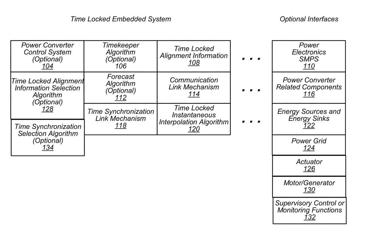
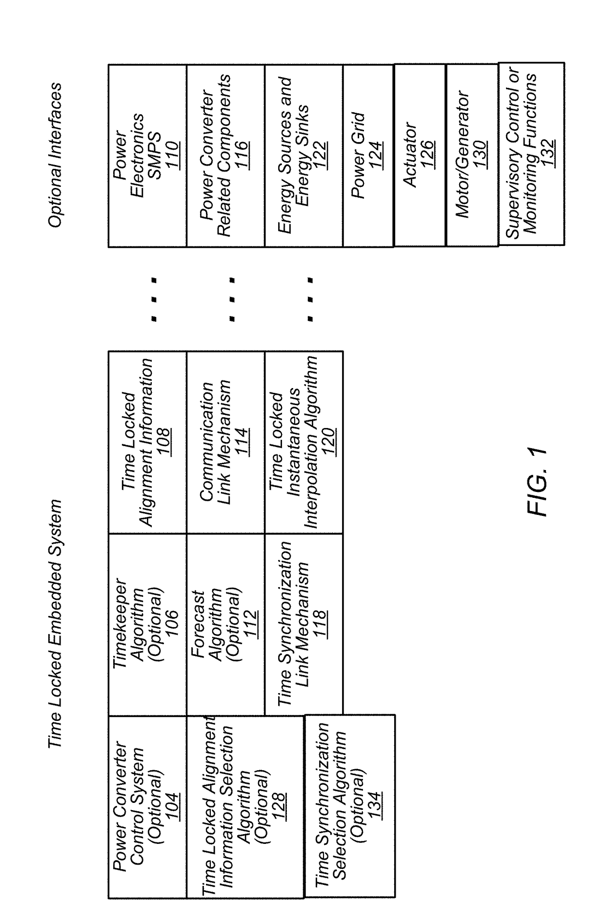
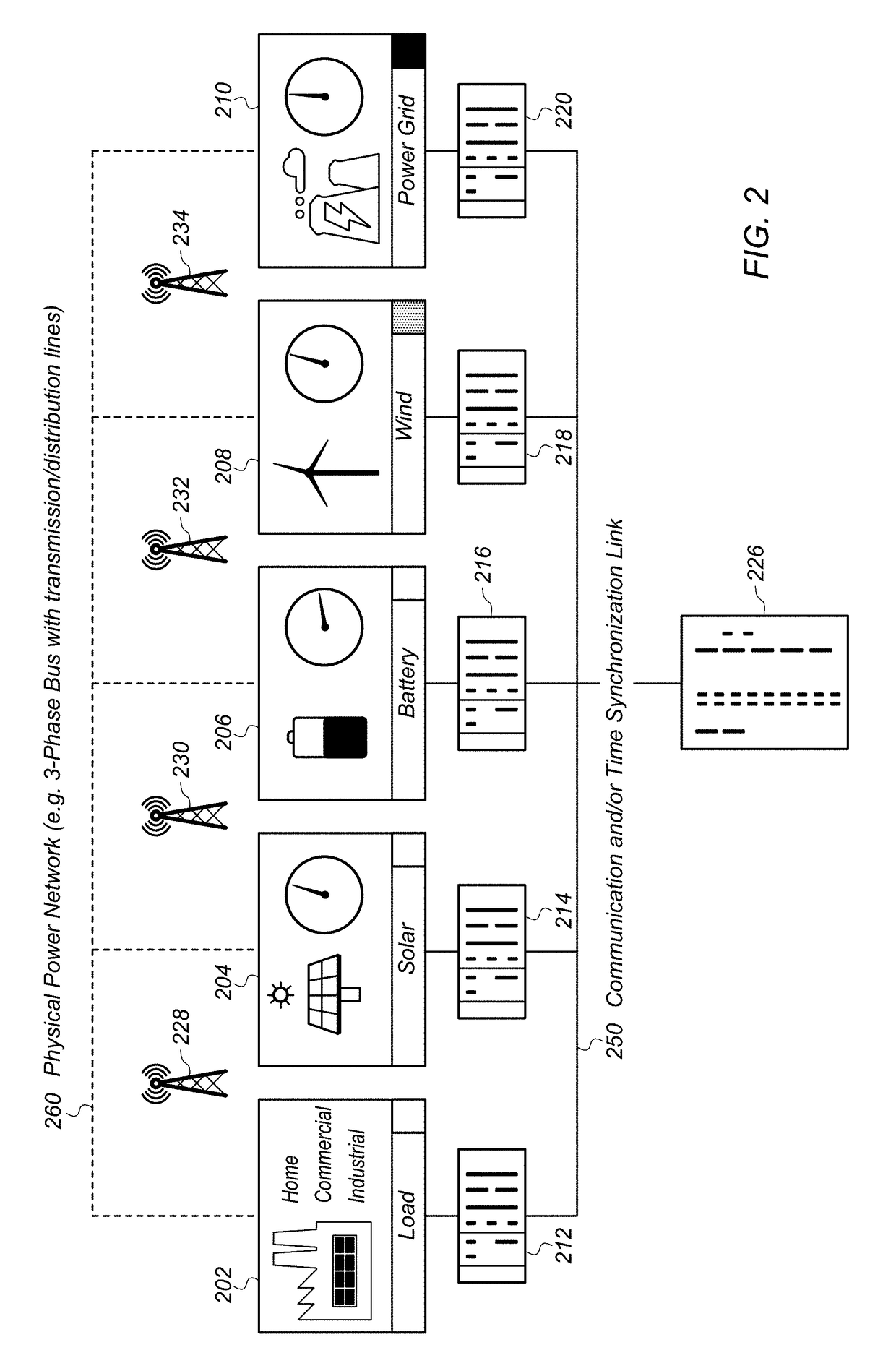
[0028]Various embodiments disclosed herein may be used in at least improved power distribution systems that include a wide variety of power delivery means and / or power delivery devices. For example, various embodiments may be used in power distribution systems that include power delivery devices associated with traditional electro-mechanical power sources (e.g. coal fired plant with power delivered to the grid by synchronous generators) as well as more modern power sources (e.g. solar panels and wind, with power delivered to the grid...


PUM


Abstract

An embedded system may distribute, e.g. at the point of coupling to a main power grid, information corresponding to one or more operational parameters (e.g. phase angle, frequency, amplitude, etc.) of a power delivery device to other power delivery devices, using a deterministic communication link. Updates of some or all of the information may be transmitted at future or past points in time, for example at defined time intervals. Time synchronization methods, e.g. a locked instantaneous interpolation mechanism may be used to create a coordinated time, shared among all power delivery devices. Various operating parameter mismatches, e.g. a phase mismatch between power delivery devices delivering power to the power grid, may thereby be reduced to less than a specified, negligible value. This creates tight time synchronization between the power delivery devices and allows them to interoperate in a manner that stabilizes rather than destabilizes the power grid.

Description

PRIORITY CLAIM[0001]This application claims benefit of priority of U.S. Provisional Patent Application Ser. No. 62 / 399,700 titled “Time-Locked Data Alignment in Distributed Embedded Systems”, filed on Sep. 26, 2016, which is hereby incorporated by reference as though fully and completely set forth herein.FIELD OF THE INVENTION[0002]The present invention relates to the field of instrumentation and control, and more particularly to time alignment of data and information in distributed control systems and embedded systems.DESCRIPTION OF THE RELATED ART[0003]In many industrial applications (and others), instruments collect data or information from an environment or unit under test (UUT), analyze and process acquired data, and may also transmit data / control information to operate various electrical control systems. The information that may be collected and / or transmitted by respective instruments includes information describing voltage and current (amplitude, phase and frequency), resist...

Claims


Application Information

Patent Timeline
Patent Type & Authority Applications(United States)
IPC IPC(8): H02J13/00G05B19/042
CPCH02J13/0017G05B19/0423G05B2219/25232G05B2219/25474H02J3/383H02J3/386Y04S10/123H02J3/24H02J3/40H02J2300/28H02J2300/24H02J3/381H02J13/00017Y02E10/56Y02E10/76Y02E40/70Y04S40/124Y02E60/00
Inventor MACCLEERY, BRIAN C.WALTER, TODD J.SNOVER, BURT D.
Owner NATIONAL INSTRUMENTS
Why Eureka
Try Eureka