Light fixture mounting bracket

Inactive Publication Date: 2006-12-26
CORDELIA LIGHTING
View PDF11 Cites 13 Cited by
  • Summary
  • Abstract
  • Description
  • Claims
  • Application Information

AI Technical Summary

Benefits of technology

[0007]The present invention is directed to providing a lighting system that is easy for a single individual to install on a support structure without assistance, and that cannot be easily detached from the support structure. One embodiment of the invention provides that, even if the electrician encounters a variety of different wiring configurations on the support structure, the novel aspects of the invention nevertheless allow the electrician, alone and unassisted, to attach the lighting system to the support structure, even from the top of a ladder. The lighting system mount is thus versatile and highly adaptable in the field.
[0008]Three different preferred embodiment wiring and structural configurations on a support structure are described below, which enable easy installation by a single electrician. By eliminating the need for a second electrician, the labor costs involved in installing the present invention lighting system is reduced by 50 percent.

Problems solved by technology

Such a lighting system usually has a metal housing containing high voltage electrical hardware such as a transformer, a starter, etc., and includes a large, thick glass lens, all of which add to its significant collective weight.
For greatest area illumination, the lighting system also tends to be very large in size.
These factors present the electrician or installer with the awkward tasks of mounting the lighting system to a support structure and of connecting the electrical wiring of the lighting system to the power supply.
These tasks may be made all the more awkward because they are typically accomplished at the top of a ladder.
First, the mount must be constructed in at least two hinged pieces to create the swinging door effect, which increases cost and complexities during fabrication.
Second, once the mount is installed, the possibility exists that a heavier lighting system might accidentally detach and swing open from its suspended position.
This exposes the lighting system to malfunction or even tampering by unauthorized persons.
Third, the mount is designed for connection to only one type of wiring configuration found on the support surface, typically an electrical junction box recessed into a wall of a house or building.
Unfortunately, it is possible for the electrician to encounter a number of different wiring configurations and receptacles that may not be easily connected to such a mount.
For example, where the power supply wires are fed through a rigid conduit extending from the outside or the interior of the wall, or where the power supply wires protrude from the supporting surface without a J-box, connection to such varied situations may be problematic.
The Drake mount is thus not easily adaptable in the field.

Method used


Image

  • Light fixture mounting bracket
  • Light fixture mounting bracket
  • Light fixture mounting bracket

Examples


Embodiment Construction

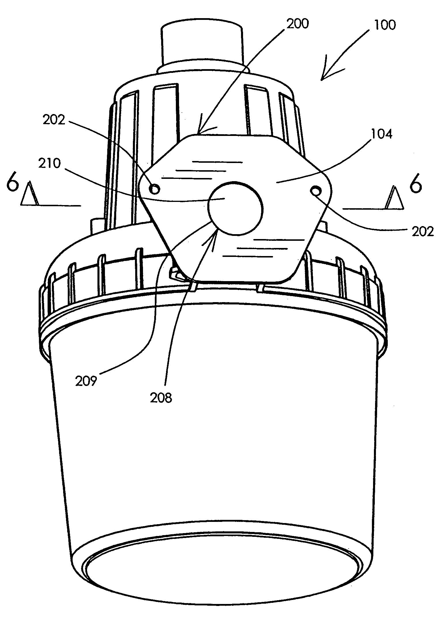
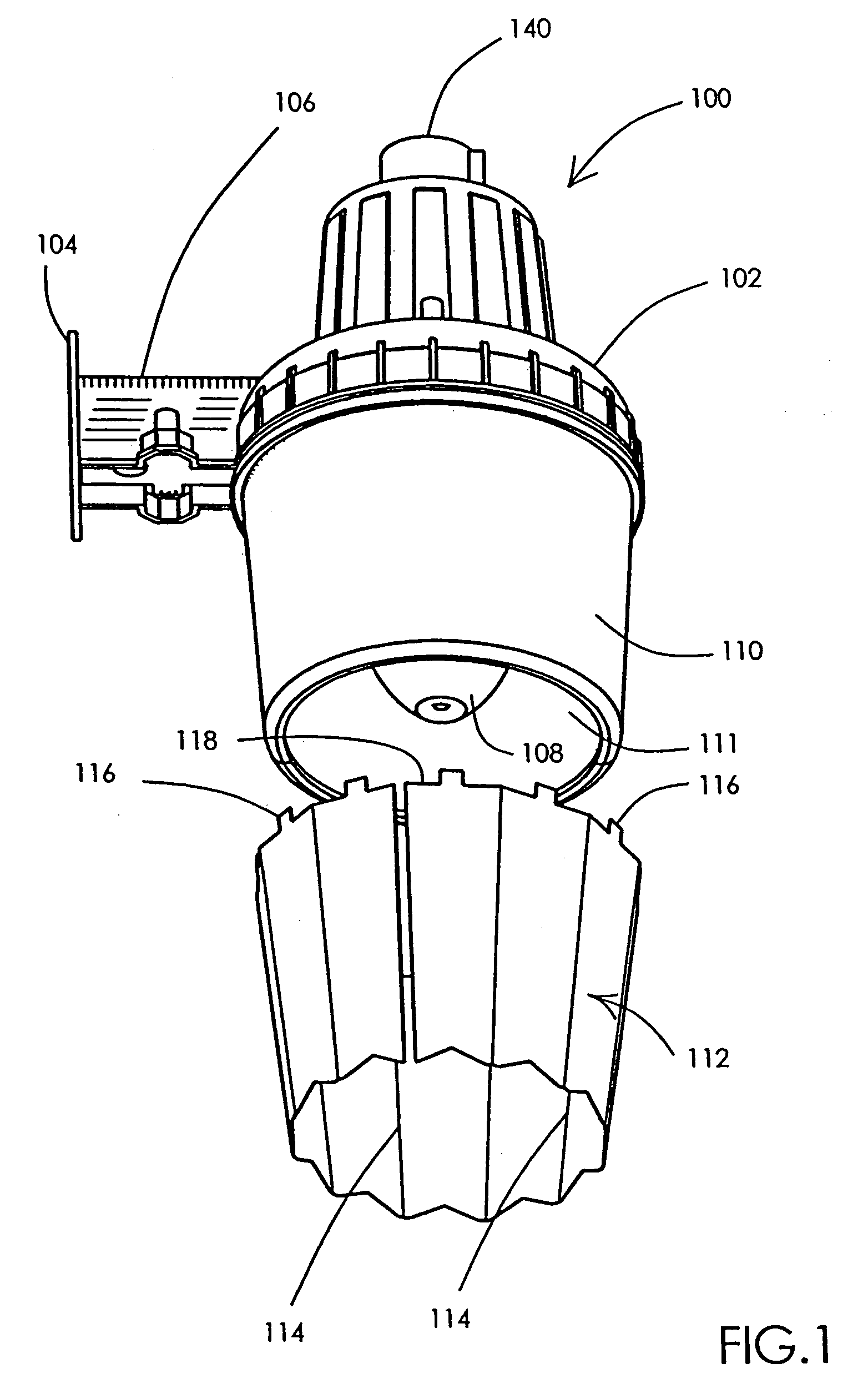
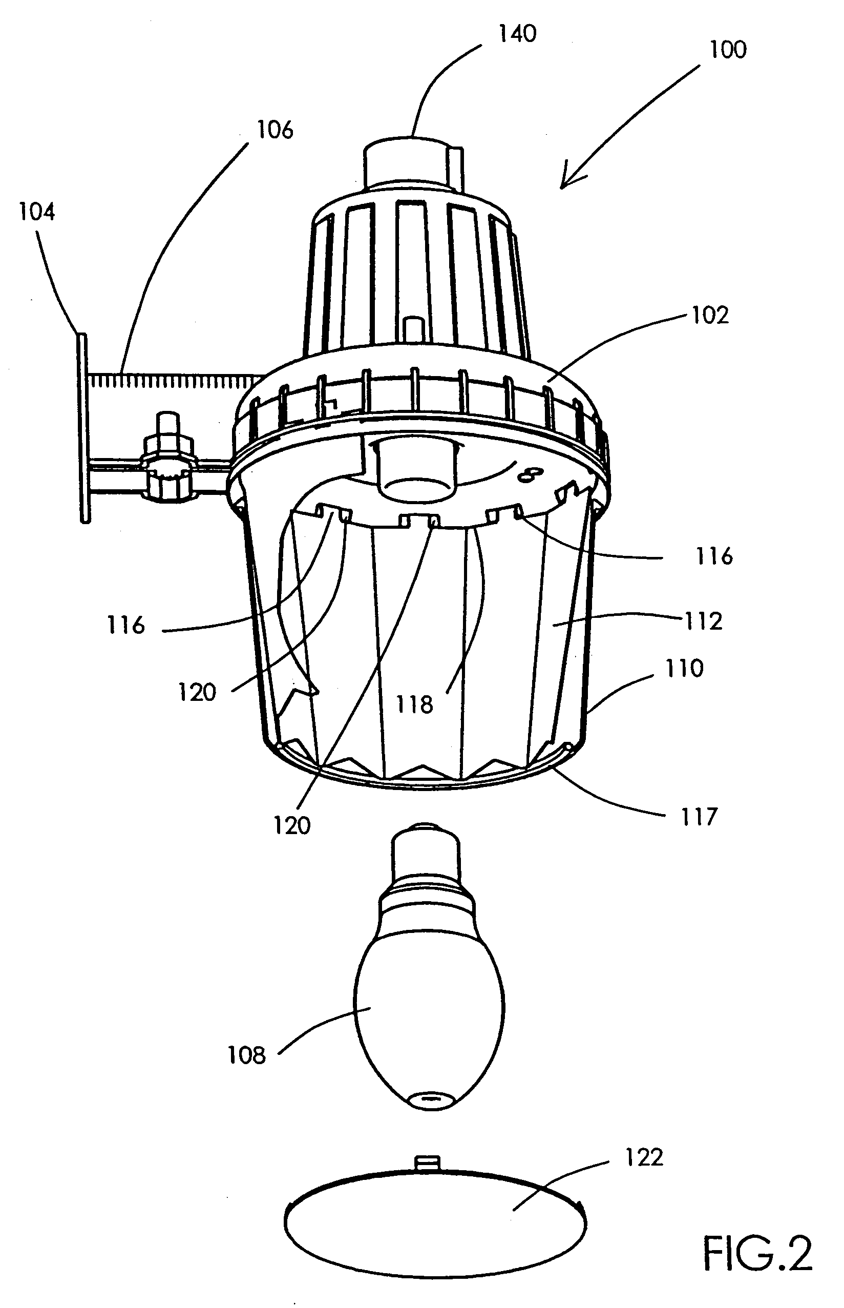
[0026]As shown in the drawing figures, which are provided for purposes of exemplary illustration, the present invention is directed to a lighting system 100. The lighting system 100 employs mounting hardware that necessitates only one electrician or technician for installation, and further benefits from mounting hardware that is easily customized and adapted in the field.

[0027]Referring to FIGS. 1–2, forming the central portion of the lighting system is a housing 102 preferably made of a metal such cast iron, steel, aluminum, bronze, plastic or the like. A hollow suspension arm 106 extends from the housing 102 and terminates with a vertical back plate 104. Preferably, these structures may be molded, cast, stamped, or machined as an integral, single piece, or they be assembled and then welded, soldered, cemented, screwed, snapped, or joined together from several pieces. The back plate 104 is configured to mount the housing 102 to a wall, post, or like permanent or semi-permanent supp...


PUM


Abstract

A lighting system including a mount for one person installation to a support surface having a rigid conduit supplying electrical wires. The lighting system includes a housing containing a light source. A hollow suspension arm extends from the housing and a back plate is located on the arm opposite the housing. The suspension arm includes a removable bottom access plate with a knock-out blank to provide optional wiring access, and the back plate includes a frangible portion. An impact blow creates an opening in the frangible portion that leads into the hollow arm. Straight and curved extension sections are provided for optional attachment to the rigid conduit. The rigid conduit is inserted through the opening in the back plate and into the arm thus suspending the lighting system therefrom.

Description

FIELD OF THE INVENTION[0001]The present invention relates generally to outdoor lighting systems, and in particular, to improved structural aspects of such lighting systems for mounting the lighting system to a structural support such as a wall or post.BACKGROUND OF THE INVENTION[0002]It is common to erect exterior lighting around domestic, industrial, public, and military property to provide security against intruders, and to provide lighting for visitors and authorized personnel. Such a lighting system usually has a metal housing containing high voltage electrical hardware such as a transformer, a starter, etc., and includes a large, thick glass lens, all of which add to its significant collective weight. For greatest area illumination, the lighting system also tends to be very large in size. These factors present the electrician or installer with the awkward tasks of mounting the lighting system to a support structure and of connecting the electrical wiring of the lighting system ...

Claims


Application Information

Patent Timeline
IPC IPC(8): F21S8/00
CPCF21V21/02F21V21/108F21V23/0442F21S8/033F21V17/104F21W2131/10F21V11/12F21V11/16
Inventor MONROE, TIM E.WANDREY, JOHN H.
Owner CORDELIA LIGHTING
Why Eureka
Try Eureka