Tape printing apparatus, tape printing apparatus charger and tape printing apparatus charging system

a charging system and tape printing technology, applied in printing, other printing apparatus, transportation and packaging, etc., can solve problems such as power interruption to the rectifying section, and achieve the effects of reducing the depth of the fitting section, mounting or removing and reducing the height of the tape printing apparatus charger

Active Publication Date: 2006-12-26
BROTHER KOGYO KK
View PDF16 Cites 14 Cited by
  • Summary
  • Abstract
  • Description
  • Claims
  • Application Information

AI Technical Summary

Benefits of technology

[0010]Thus, this tape printing apparatus charging system allows the tape printing apparatus to be charged when the tape printing apparatus is stood on the tape printing apparatus charger with the second side face section of the tape printing apparatus facing downward. Consequently, the tape printing apparatus charger may be placed in a small space on a desk top to recharge the tape printing apparatus, thereby saving space for the tape printing apparatus charging system.
[0012]Because the first supporting section of the tape printing apparatus charger in the tape printing apparatus charging system is formed to a predetermined height from four sides of the bottom face section in the fitting section for supporting the vicinity section of the second side face section of the tape printing apparatus, the depth of the fitting section can be decreased and the height of the tape printing apparatus charger can be reduced.
[0013]Because the tape printing apparatus can be mounted by inserting a section inside a predetermined distance from each side of the top face section and outside of the key input unit and display unit, the tape printing apparatus can be set to the tape printing apparatus charger smoothly from a free angle, such as from obliquely upward, or forward direction. Further, when mounting or removing the tape printing apparatus on / from the tape printing apparatus charger, the tape printing apparatus can be mounted or removed on / from the tape printing apparatus charger easily by gripping the top face section and bottom face section and sliding the pieces in the appropriate direction.

Problems solved by technology

When the electronic apparatus is removed from the insertion concave section, the charging contact pieces are separated from the contact pieces thereby interrupting power to the rectifying section.

Method used


Image

  • Tape printing apparatus, tape printing apparatus charger and tape printing apparatus charging system
  • Tape printing apparatus, tape printing apparatus charger and tape printing apparatus charging system
  • Tape printing apparatus, tape printing apparatus charger and tape printing apparatus charging system

Examples


Embodiment Construction

[0034]An exemplary embodiment of the tape printing apparatus, tape printing apparatus charger and charging system using the tape printing apparatus and the tape printing apparatus charger of the invention will be described in detail with reference to the accompanying drawings.

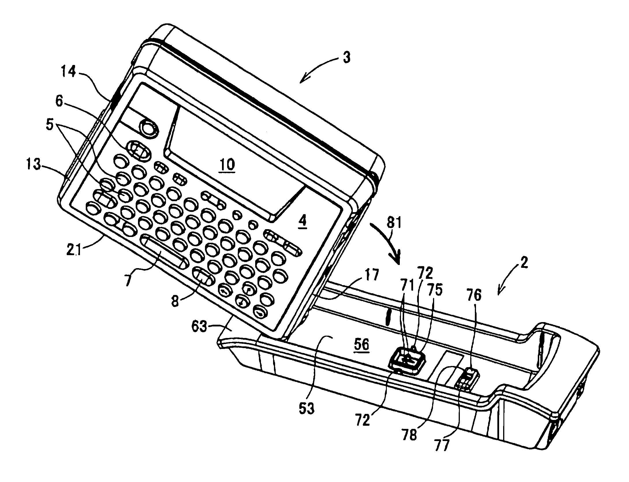
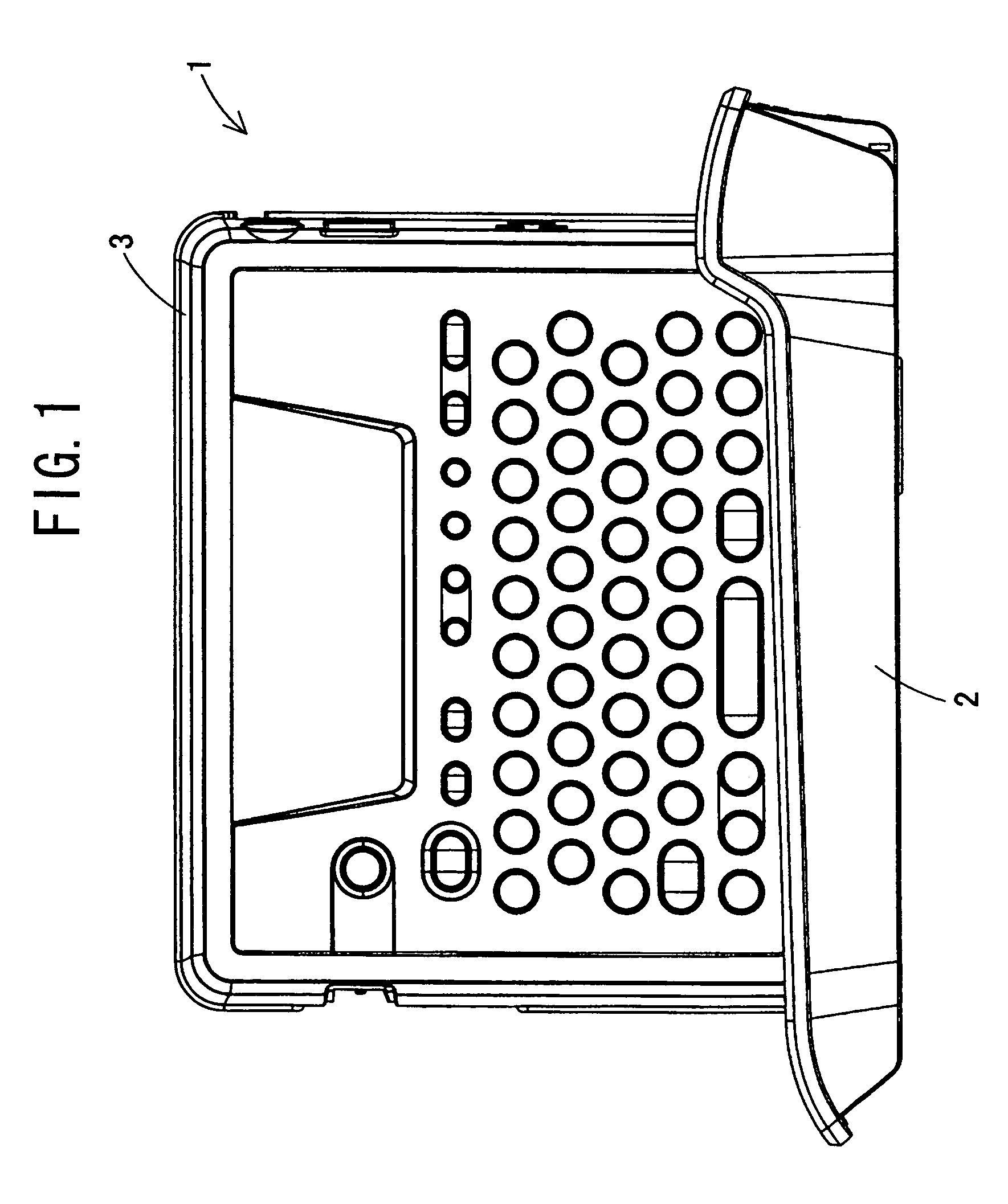
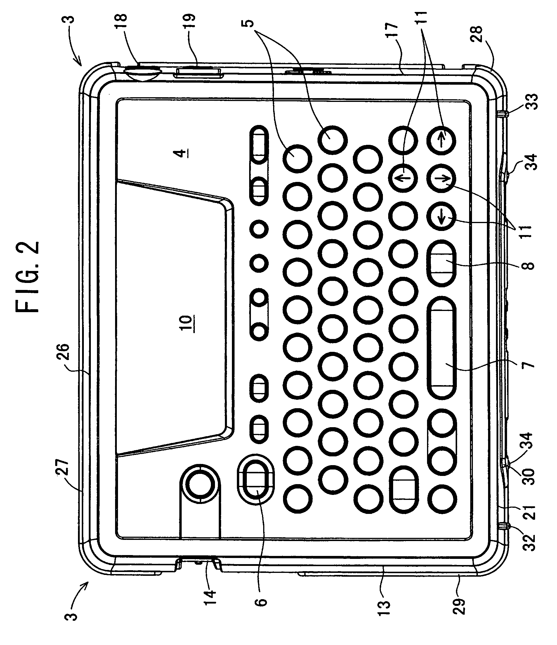
[0035]According to one aspect of the invention, there is provided a tape printing apparatus, which has a substantially thin, box shape, comprising a key input unit having a plurality of input keys and a display unit disposed on a top face section, a tape discharge slot that discharges a tape on which characters input or edited with the key input unit, or the like, are printed is provided on a first side face section. A second side face section, perpendicular to the first side face section, is provided with a charging power receiving terminal. The key input unit and display unit are disposed at least within a section at a predetermined distance from each side of a top face section connected to the first side fac...


PUM


Abstract

A tape printing apparatus that can be set smoothly into a tape printing apparatus charger from a free angle by gripping the top face section and the bottom face section of the tape printing apparatus such that the front side face section faces downward and the right side face section faces the forward direction, the lower edge on the right side face section of the tape printing apparatus is placed on the forward section of the fitting section from an angle obliquely upward of the tape printing apparatus charger. With the front side face section of the tape printing apparatus kept in contact with the top edge on the front side wall section of the fitting section of the tape printing apparatus charger, the tape printing apparatus is inserted into the tape printing apparatus charger in the forward direction for recharging.

Description

[0001]This application claims priority from JP 2003-330850 filed on Sep. 24, 2003, the disclosure of which is incorporated in its entirety herein by reference thereto.BACKGROUND OF THE INVENTION[0002]1. Field of Invention[0003]The invention relates to a chargeable tape printing apparatus, a tape printing apparatus charger and a tape printing apparatus charging system using the tape printing apparatus and the tape printing apparatus charger.[0004]2. Description of Related Art[0005]Conventionally, many kinds of chargeable electronic apparatuses and chargers have been proposed.[0006]For example, Japanese Patent Application Laid-Open No.SHO64-60232 discloses a charger for an electronic apparatus comprising a case and a rectifier provided within the case. A fitting section is formed in the case so that an electronic apparatus may be mounted therein. A pair of charging contact pieces, which are movably supported in the insertion direction of the electronic apparatus, are disposed on the b...

Claims


Application Information

Patent Timeline
Patent Type & Authority Patents(United States)
IPC IPC(8): B41J3/39B41J3/407H02J7/00
CPCB41J3/4075H02J7/0044
Inventor TAKAHASHI, TOSHIHIRO
Owner BROTHER KOGYO KK
Why Eureka
Try Eureka