Rotor system vibration absorber

a technology of vibration absorber and rotating hub, which is applied in the direction of machines/engines, liquid fuel engines, other chemical processes, etc., can solve problems such as system failure safety, and achieve the effects of minimizing vibration, minimizing vibration, and minimizing maintenan

Inactive Publication Date: 2006-12-26
BELL HELICOPTER TEXTRON INC
View PDF8 Cites 12 Cited by
  • Summary
  • Abstract
  • Description
  • Claims
  • Application Information

AI Technical Summary

Benefits of technology

[0007]There is a need for a rotor system vibration absorber for use on a helicopter or other rotorcraft that can be installed above and / or below the rotor hub for minimizing vibration due to both in-plane hub shear forces and out-of plane hub bending moments, and that requires little or no maintenance.
[0008]Therefore, it is an object of the present invention to provide a weight-efficient rotor system vibration absorber for use on a helicopter or other rotorcraft that can be installed above and / or below the rotor hub for minimizing vibration due to both in-plane hub shear forces and out-of-plane hub bending moments, and that requires little or no maintenance.
[0009]The above object is achieved by providing a rotor system vibration absorber having a simple, low-cost design in which a plurality of elongated rods are arranged in a selected pattern. Each rod is coupled at one end to the rotor hub, and at the opposing end to a tuning weight.
[0010]The vibration absorber of the present invention provides the following significant advantages over the prior art. The vibration absorber according to the present invention has a simple, low-cost design having no moving parts. This feature significantly reduces wear and maintenance. Each rod provides an independent load path, thereby making the system fail safe. In the present invention, over 80% of the weight of the vibration absorber is utilized as a tuning weight, thereby eliminating the weight inefficiencies present in prior-art devices. The vibration absorber of the present invention can be installed above and / or below the rotor hub. This allows it to counteract not only in-plane hub shear forces, but out-of-plane hub bending moments, i.e., roll and pitch. The rotor system vibration absorber of the present invention is easily maintainable in the field because it is has a high level of reliability and failures are easily detectable.

Problems solved by technology

Each rod provides an independent load path, thereby making the system fail safe.

Method used


Image

  • Rotor system vibration absorber
  • Rotor system vibration absorber
  • Rotor system vibration absorber

Examples


Embodiment Construction

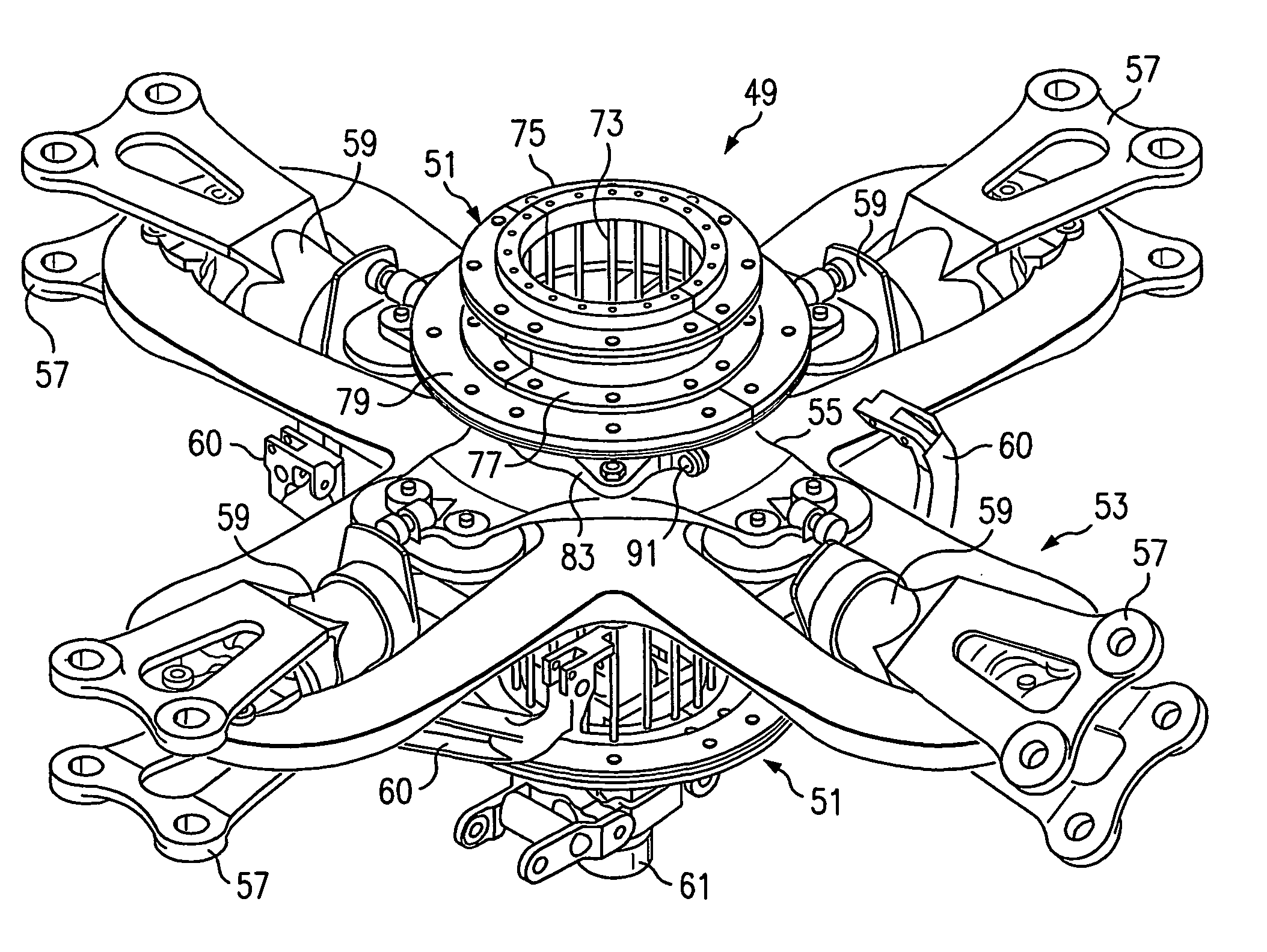
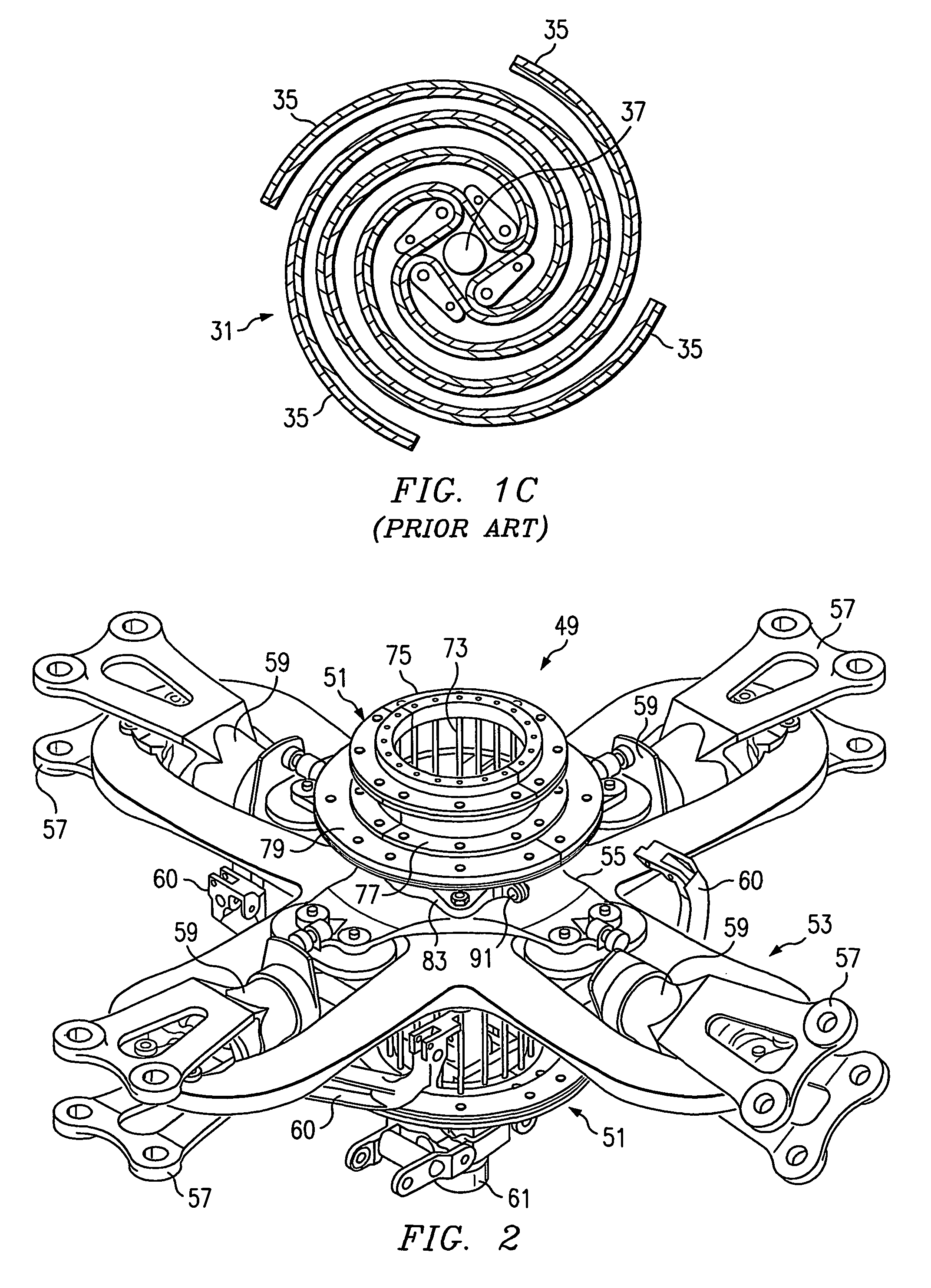
[0027]Referring to FIG. 2 in the drawings, one simplified embodiment a rotor system 53 with a vibration absorber 51 according to the present invention is illustrated. Vibration absorber 51 counteracts rotor induced vibration from rotor system 53 of a helicopter or other rotorcraft. In particular, vibration absorber 51 is a spring-mass system that is dynamically tuned to reduce the principal blade-passage frequency vibration in rotor system 53. Vibration absorber 51 is capable of counteracting both in-plane forces and out-of-plane moments without the use of complicated moving parts. The in-plane forces are vibratory shear forces that generally act in the plane of a rotor hub 55, and the out-of-plane moments are generally vibratory bending moments about axes that lie in the plane of hub 55, i.e., moments caused by roll and pitch. The plane of hub 55 will be referred to herein as the rotor plane.

[0028]The present invention may be utilized in any of the following implementations: (1) wi...


PUM


Abstract

A rotor system vibration absorber for use with a helicopter of other rotorcraft is disclosed in which spring forces are provided by a plurality of elongated rods arranged in a selected pattern. The rods are coupled at one end to a fixed base that is coupled to a rotor hub, and at the other end to a tuning weight.

Description

TECHNICAL FIELD[0001]The present invention relates to vibration absorbers. In particular, the present invention relates to rotor hub vibration absorbers for helicopters and other rotorcraft.DESCRIPTION OF THE PRIOR ART[0002]Rotor induced vibration is a major environmental factor in helicopter operations. The main source of rotor induced vibration is the inherent excitation caused by transverse airflow into the rotating wing. While every effort is made during the design stage to overcome this problem by careful design of the rotor and fuselage, it is sometimes necessary to employ parasitic devices, such as vibration absorbers, to reduce this rotor system vibration. One such method is to install vibration absorbers at the rotor hub. By installing vibration absorbers at the rotor hub, the inherent rotor excitation caused by the transverse airflow into the rotor can be minimized at the source of the problem.[0003]A common form of rotor head vibration absorber is the pendulum, both stand...

Claims


Application Information

Patent Timeline
Patent Type & Authority Patents(United States)
IPC IPC(8): B64C27/51B64C27/00
CPCB64C27/001B64C27/51B64C2027/003Y10S416/50
Inventor SEHGAL, AJAYSMITH, MICHAEL R.STAMPS, FRANK B.MARSHALL, BRYANCOVINGTON, LEGAL REPRESENTATIVE, PEGGYCOVINGTON, DECEASED, CECIL E.
Owner BELL HELICOPTER TEXTRON INC
Why Eureka
Try Eureka