
Power tool level indicator

a technology of level indicator and power tool, which is applied in the field of level indicator, can solve the problems of still burdening the user to view the bubble between the lines, the level type of the bubble is not conducive to vertical drilling, and the level is useless in many applications, and achieves the effect of convenient use of leveling

Inactive Publication Date: 2006-12-26
BLACK & DECKER INC
View PDF20 Cites 26 Cited by
  • Summary
  • Abstract
  • Description
  • Claims
  • Application Information

AI Technical Summary

Benefits of technology

[0006]Accordingly, it is an object of the present invention to provide a user with an easy to use leveling device. The device indicates to the user, usually by an illuminated light, that horizontal or vertical planes have been achieved. The present invention enables the user to readily establish visual contact to indicate that a desired plane has been achieved.

Problems solved by technology

While the bubble level works satisfactorily for horizontal applications, it is still burdensome on the user to view the bubble in between the lines.
Ordinarily, these bubble types of levels are not conducive for vertical drilling.
Also, due to the vibration of the tool, frothing occurs inside the level, rendering the bubble level useless in many applications.
Also, while these types of devices may be satisfactory for horizontal planes, they are not particularly useful when used in a vertical drilling arrangement.

Method used


Image

  • Power tool level indicator
  • Power tool level indicator
  • Power tool level indicator

Examples


Embodiment Construction

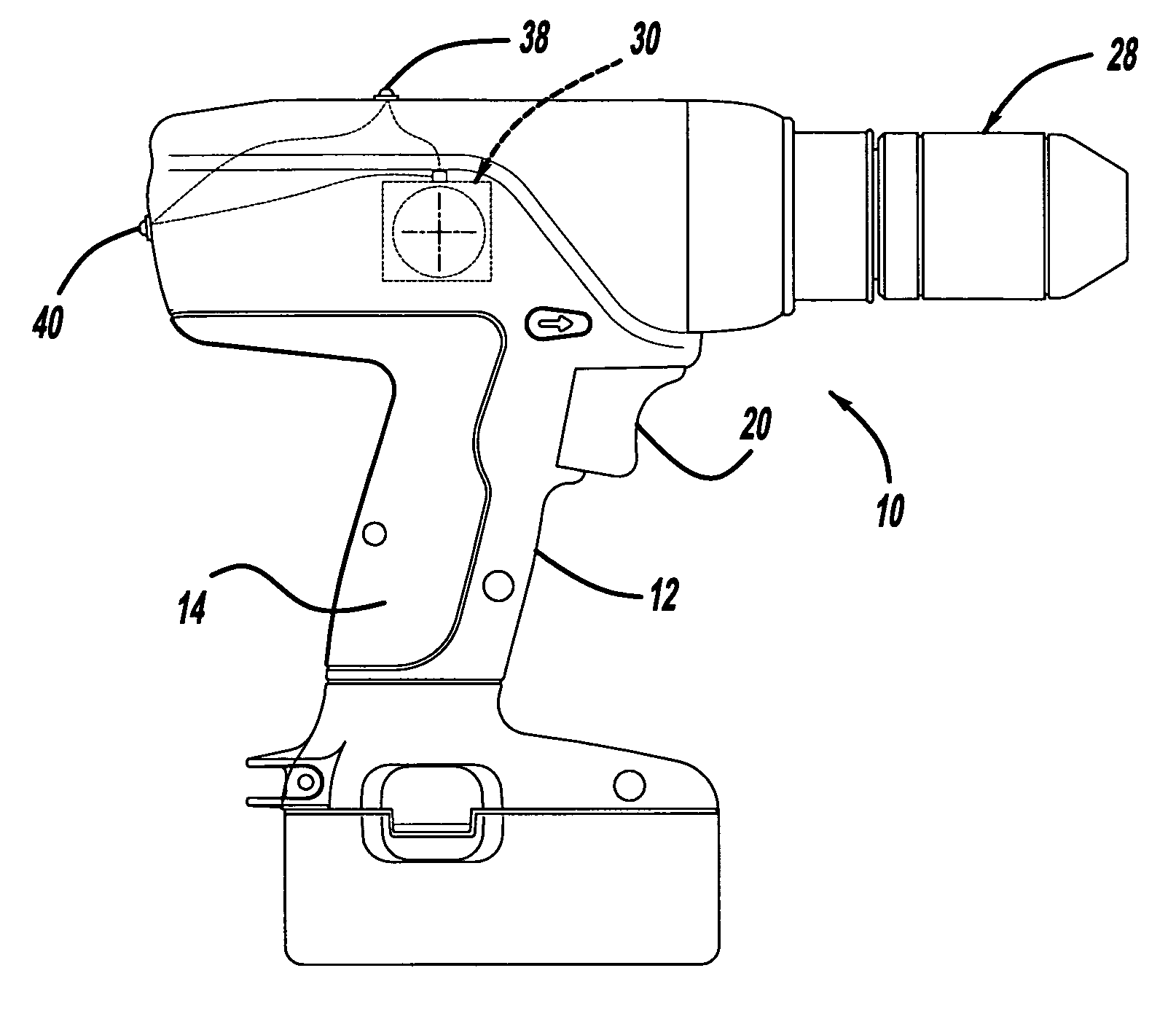
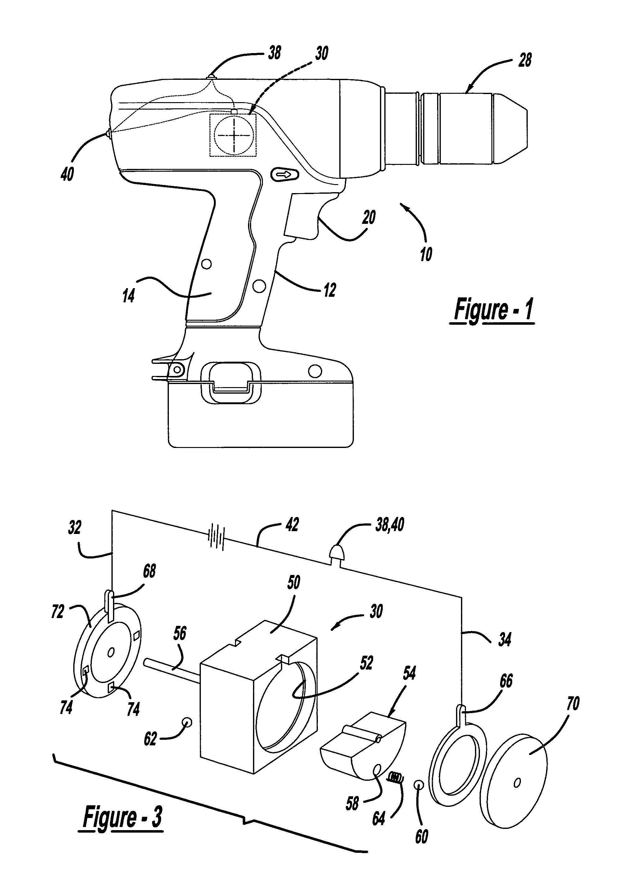
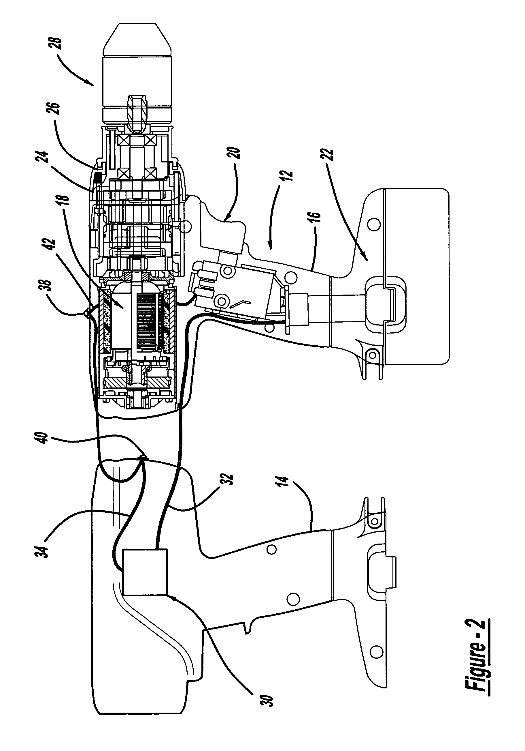
[0015]Turning to the figures, FIG. 1 illustrates a power tool in accordance with the present invention and is designated with the reference numeral 10. The power tool 10 is illustrated as a drill; however, any type of power tool such as a screwdriver, sander, rotary tool, clippers, saw or the like can be utilized with the level indicator in accordance with the present invention. The power tool 10 includes a housing 12 which includes two halves 14 and 16, which surround a motor 18. An activation member 20 is coupled with the motor 18 as well as with a power source 22. The power source 22 may be a power cord (AC current) or the power tool may have a battery (DC current) as shown. The motor 18 is coupled with an output 24 which may include a transmission 26 and a chuck 28 to retain a tool (not shown) with the drill.

[0016]Looking at housing half 14 in FIG. 2, a level indicator is shown and designated with the reference numeral 30. The level indicator 30 has wires 32 and 34 extending the...


PUM


Abstract

A power tool includes a leveling mechanism that determines horizontal or vertical planes of the power tool. The leveling mechanism has a housing with a cavity in the housing. A rotating member is in the housing. The rotating member moves in the cavity such that the rotating members seeks an equilibrium position. The equilibrium position corresponds to a horizontal or vertical plane. Electrical contacts are coupled with the rotating member such that the electrical contacts only complete an electrical circuit when the rotating member is in the equilibrium position. An indicator is electrically coupled with the electrical contacts to indicate to the user when the mechanism is in an equilibrium position. A power source is coupled with the electrical contacts and the indicator to energize the indicator when the circuit is complete.

Description

BACKGROUND AND SUMMARY OF THE INVENTION[0001]The present invention relates to power tools and, more particularly, to a leveling device that indicates when the power tool is in a horizontal or vertical plane.[0002]In various types of power tools, especially drilling tools, it is desirable to know when the tool is in a horizontal or vertical plane. This is particularly useful when drilling holes for hanging doors or the like when it is desirable to have holes which are in plane with horizontal.[0003]Bubble type of levels have been utilized in power tools. However, these types of leveling devices have various shortcomings. While the bubble level works satisfactorily for horizontal applications, it is still burdensome on the user to view the bubble in between the lines. Ordinarily, these bubble types of levels are not conducive for vertical drilling. Also, due to the vibration of the tool, frothing occurs inside the level, rendering the bubble level useless in many applications.[0004]An...

Claims


Application Information

Patent Timeline
IPC IPC(8): G08B21/00B25F5/02
CPCB25F5/022
Inventor JUDGE, ALFRED H.
Owner BLACK & DECKER INC
Learn More