Nanocrystalline core antenna for EAS and RFID applications

a technology of nanocrystalline core and core antenna, which is applied in the direction of loop antennas with ferromagnetic cores, near-field systems using receivers, transmission, etc., can solve the problems of permeability reducing performance at frequencies higher than a few 100 khz, and amorphous magnetic materials that do not perform well in the rf frequency, so as to achieve the effect of expanding the detection rang

Active Publication Date: 2006-12-26
SENSORMATIC ELECTRONICS CORP
View PDF11 Cites 41 Cited by
  • Summary
  • Abstract
  • Description
  • Claims
  • Application Information

AI Technical Summary

Benefits of technology

[0010]A method of establishing extended detection range in an EAS or RFID system consistent with the invention includes: providing a nanocrystalline core antenna including a core and at least one coil winding disposed around at least a portion of the core, the core including nanocrystalline magnetic material; and exciting the antenna for operation up to and including RF frequency.

Problems solved by technology

However, such amorphous magnetic materials do not perform well in the RF frequency range as core loss and permeability decrease performance for frequencies higher than a few 100 kHz.

Method used


Image

  • Nanocrystalline core antenna for EAS and RFID applications
  • Nanocrystalline core antenna for EAS and RFID applications
  • Nanocrystalline core antenna for EAS and RFID applications

Examples


Embodiment Construction

[0022]For simplicity and ease of explanation, the present invention will be described herein in connection with various exemplary embodiments thereof associated with EAS systems. A core antenna consistent with the present invention may, however, be used in connection with an RFID system. It is to be understood, therefore, that the embodiments described herein are presented by way of illustration, not of limitation.

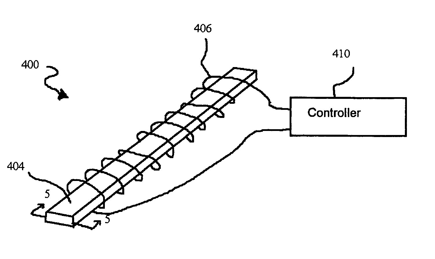
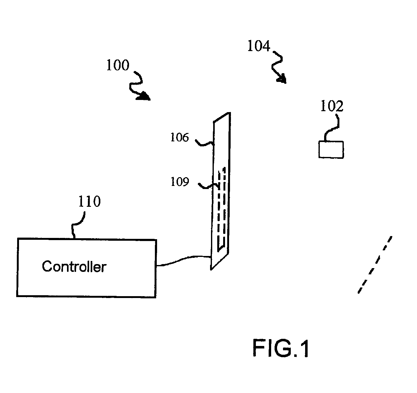
[0023]Turning to FIG. 1, there is illustrated an EAS system 100 including a nanocrystalline core antenna 109 consistent with the invention. The EAS system 100 generally includes a controller 110 and a pedestal 106 for housing the core antenna 109. The controller 110 is shown separate from the pedestal 106 for clarity but may be included in the pedestal housing. In the exemplary embodiment of FIG. 1, the antenna 109 is configured as a transceiver and the associated controller 110 includes proper control and switching to switch from transmitting to receiving functions at pre...


PUM


Abstract

A nanocrystalline core antenna for use in electronic article surveillance (EAS) and radio frequency identification (RFID) systems. The nanocrystalline antenna is constructed from nanocrystalline material and exhibits improved detection range in EAS and RFID systems compared to conventional antenna configurations.

Description

FIELD OF THE INVENTION[0001]The present invention relates to core antennas, and, in particular, to core antennas for electronic article surveillance (EAS) and radio frequency identification (RFID) systems.BACKGROUND[0002]EAS and RFID systems are typically utilized to protect and / or track assets. In an EAS system, an interrogation zone may be established at the perimeter, e.g. at an exit area, of a protected area such as a retail store. The interrogation zone is established by an antenna or antennas positioned adjacent to the interrogation zone.[0003]EAS markers are attached to each asset to be protected. When an article is properly purchased or otherwise authorized for removal from the protected area, the EAS marker is either removed or deactivated. If the marker is not removed or deactivated and moved into the interrogation zone, the electromagnetic field established by the antenna(s) causes a response from the EAS marker. An antenna acting as a receiver detects the EAS marker's re...

Claims


Application Information

Patent Timeline
Patent Type & Authority Patents(United States)
IPC IPC(8): H01Q7/08H01Q1/22H04B5/02H04B5/00H04B7/00
CPCH01Q1/22H01Q1/2216H01Q7/08H04B5/02B82Y30/00
Inventor COPELAND, RICHARD L.KEITH, EDDIE H.
Owner SENSORMATIC ELECTRONICS CORP
Why Eureka
Try Eureka