
Sharpness improvement apparatus for video signals

a video signal and sharpness improvement technology, applied in the field of display devices, can solve the problems of inability to obtain the desired second differentiation signal precisely, the inability of the display device, the receiver and the monitor, etc., and achieve the effect of improving the degradation phenomenon of the signal generated and simple digital circui

Inactive Publication Date: 2006-12-26
LG ELECTRONICS INC
View PDF13 Cites 5 Cited by
  • Summary
  • Abstract
  • Description
  • Claims
  • Application Information

AI Technical Summary

Benefits of technology

The present invention provides a digital sharpness improvement apparatus that can improve the sharpness of signals generated at analog image processing. This apparatus can be used in high definition television (HDTV) receivers or computer system monitors to improve the display quality. The apparatus includes an image source processing unit, an analog image processing unit, a digital sharpness improvement unit, and a display unit. The image source processing unit performs a predetermined image process on an image signal. The analog image processing unit converts the processed signal into R, G, and B signals for display. The digital sharpness improvement unit enhances the sharpness of the R, G, and B signals by improving the quality of the image. The display unit then displays the improved sharpness signals on a screen. Overall, this invention provides a simple and effective solution to improve image quality and sharpness for various display devices.

Problems solved by technology

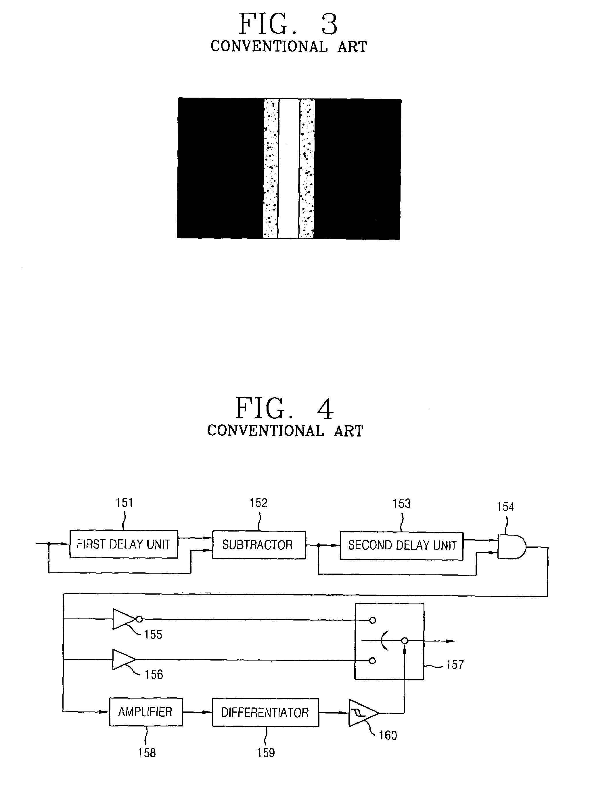
Generally, a display device such as a television receiver and a monitor can not realize a clear image when an image signal of a received signal or an analogue image signal inputted from a computer system is processed into a predetermined analogue such as an amplification and a conversion because an edge characteristic of the image signal is deteriorated.
Also, since the sharpness improving apparatuses 150 are all composed of analogue devices, a wanted second differentiation signal can not be precisely obtained.
In addition, even though the sharpness improvement can be done softly so as to reduce the ringing phenomenon, said method has a limitation to achieve the sharpness improvement of the inputted R, G, and B signals as wanted.

Method used


Image

  • Sharpness improvement apparatus for video signals
  • Sharpness improvement apparatus for video signals
  • Sharpness improvement apparatus for video signals

Examples


Embodiment Construction

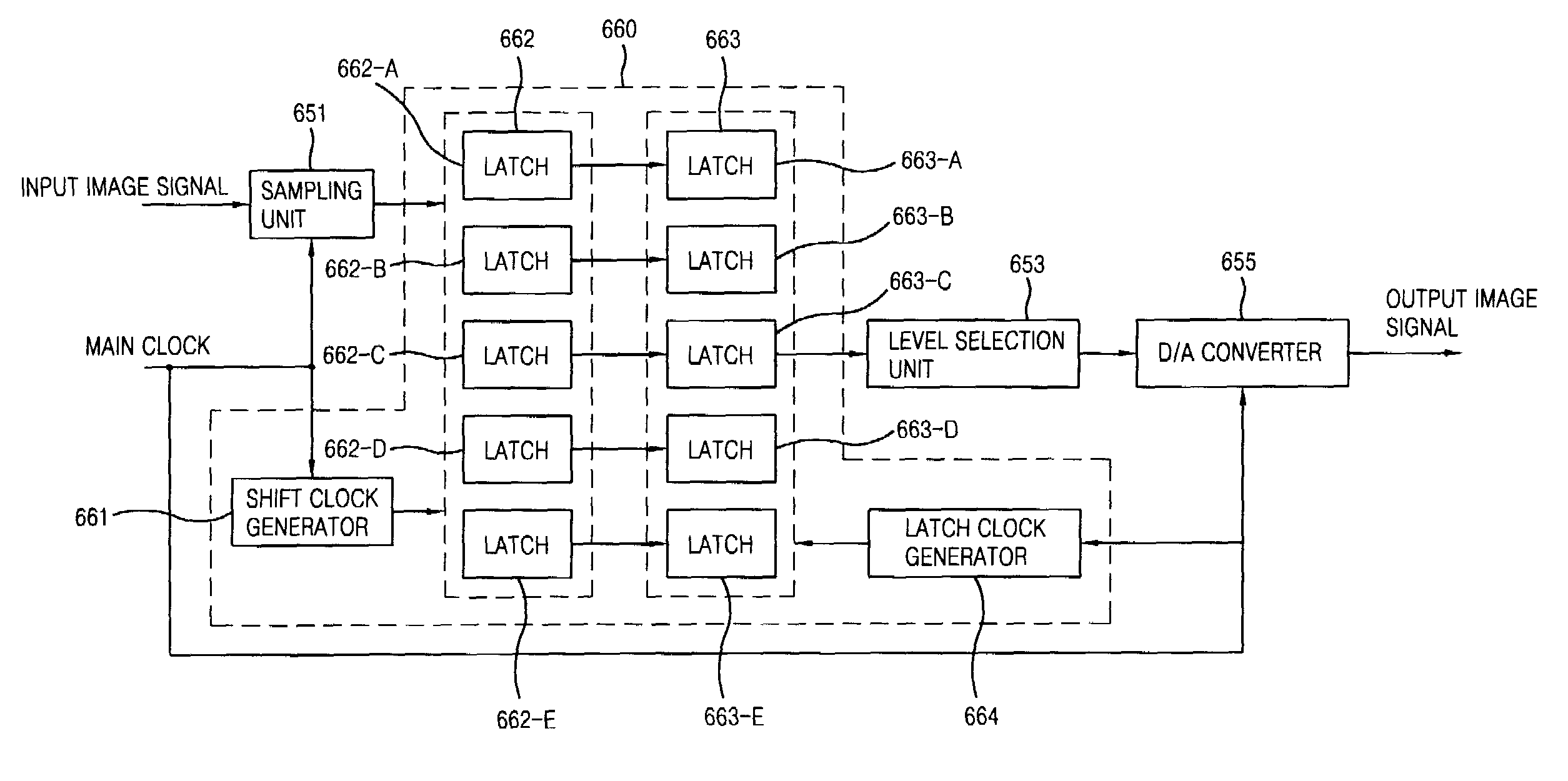
[0038]Reference will now be made in detail to the preferred embodiments of the present invention, examples of which are illustrated in the accompanying drawings. FIG. 6 is a block diagram showing a display device to which a digital sharpness improving apparatus is applied according to the present invention. The display device comprises: an image source processing unit 610 for performing a predetermined image process by receiving an image signal; an analogue image processing unit 630 for outputting R, G, and B signals which can be displayed by receiving the signal processed in the image source processing unit 610; a digital sharpness improvement unit 650 for improving a sharpness of the R, G, and B signals by receiving the R, G, and B signals processed in the analogue image processing unit 630; and a display unit 670 for receiving the R, G, and B signals having an improved sharpness and then displaying on a screen.

[0039]Operations of the display device will be explained.

[0040]First, ...


PUM


Abstract

Disclosed is a sharpness improvement apparatus of an image signal which improves a sharpness of an analogue image signal so as to display a clear image. A display device which displays an inputted image signal on a screen can display a clear image with a digital sharpness improvement apparatus which realizes a sharpness of the image signal into a digital method by improving a degradation phenomenon of a signal generated at an analogue image processing into a simple digital circuit.

Description

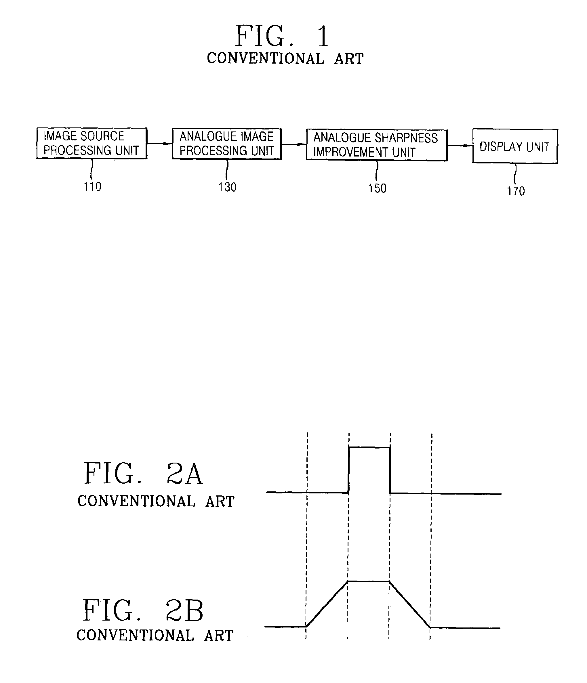
BACKGROUND OF THE INVENTION[0001]1. Field of the Invention[0002]The present invention relates to a display device, and more particularly, to a sharpness improvement apparatus for analogue videos signals to display a clear image in a display device such as a television receiver and a monitor.[0003]2. Description of the Background Art[0004]Generally, a display device such as a television receiver and a monitor can not realize a clear image when an image signal of a received signal or an analogue image signal inputted from a computer system is processed into a predetermined analogue such as an amplification and a conversion because an edge characteristic of the image signal is deteriorated.[0005]FIG. 1 is a block diagram showing a display device to which a sharpness improvement apparatus according to the conventional art is applied. The display device comprises an image source processing unit 110 for performing a predetermined image process by receiving an image signal; an analogue ima...

Claims


Application Information

Patent Timeline
Patent Type & Authority Patents(United States)
IPC IPC(8): H04N5/21H04N5/14H04N5/208
CPCH04N5/208H04N5/14
Inventor JEONG, SANG SIK
Owner LG ELECTRONICS INC
Learn More