Magnetoresistive element and magnetic head

a technology of magnetoresistance and magnetic head, applied in the direction of magnetic body, head with metal sheet core, instruments, etc., can solve the problems of undesirable decrease in the magnetoresistance ratio and greatly decreased magnetoresistance ratio, and achieve the effect of reducing the negative effect of bias voltag

Inactive Publication Date: 2006-12-26
WESTERN DIGITAL TECH INC
View PDF12 Cites 154 Cited by
  • Summary
  • Abstract
  • Description
  • Claims
  • Application Information

AI Technical Summary

Problems solved by technology

However, magnetic transducing elements based on the above-described ferromagnetic tunneling junction of the prior art are plagued by a problem in which, generally, when a bias voltage of from several tens to several hundreds of millivolts is applied, the magnetoresistance ratio is greatly decreased.
Such a decrease in magnetoresistance ratio accompanying application of a bias voltage is undesirable for purposes of practical application of ferromagnetic tunneling junction magnetic transducing elements.

Method used


Image

  • Magnetoresistive element and magnetic head
  • Magnetoresistive element and magnetic head
  • Magnetoresistive element and magnetic head

Examples


Embodiment Construction

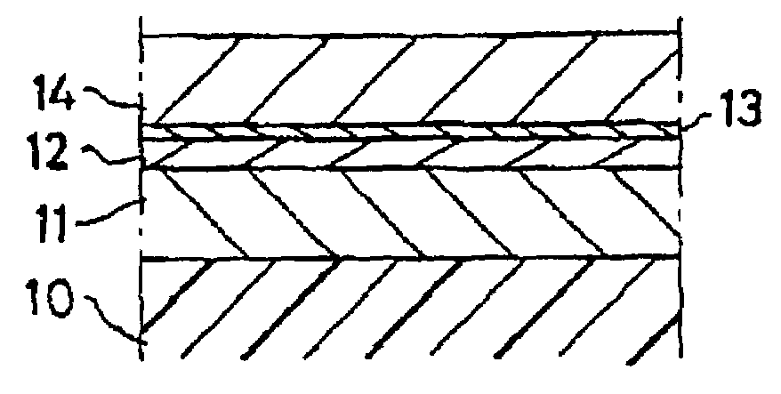
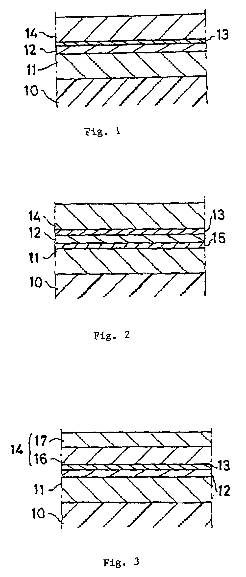
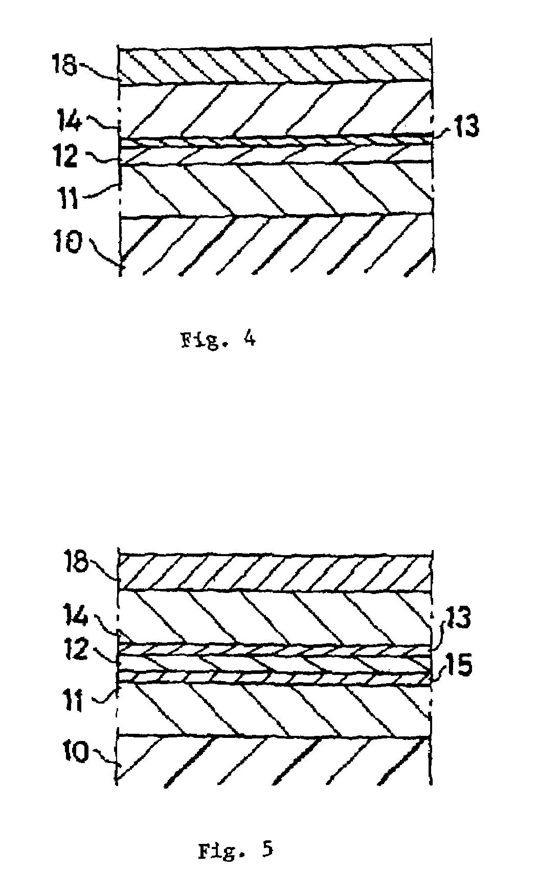
[0034]The present invention was devised in consideration of the aforementioned problem of the prior art; its objective is to suppress the decrease in magnetoresistance ratio due to application of a bias voltage, to provide a ferromagnetic tunneling junction magnetoresistive element suited for use in a variety of applications. In addition, another objective of the present invention is to provide a magnetic head, equipped with such a magnetoresistive element with high magnetoresistance ratio, for use at higher recording densities. The present invention is intended to achieve the aforementioned objectives, and is explained below using a working example illustrated in the drawings.

[0035]The present invention provides a practical application of magnetoresistive elements utilizing the magnetoresistance effect based on a ferromagnetic tunneling junction. The present invention eliminates or considerably limits the generation of magnons occurring at the insulating layer / ferromagnetic layer t...


PUM

PropertyMeasurementUnit
thicknessaaaaaaaaaa
temperatureaaaaaaaaaa
bias voltageaaaaaaaaaa

Abstract

A magnetic transducing element in which a ferromagnetic tunneling junction film, including first and second ferromagnetic layers and an insulating layer are enclosed between the ferromagnetic layers, and a nonmagnetic metal thin film is inserted between the second ferromagnetic layer and the insulating layer, is formed on a substrate.

Description

[0001]The present application is a divisional application of Ser. No. 09 / 325,888, now U.S. Patent No. 6,597,548, filed Jun. 4, 1999.BACKGROUND OF THE INVENTION[0002]1. Field of the Invention[0003]The present invention concerns a magnetic transducing element utilizing the magnetoresistance effect of a ferromagnetic tunneling junction consisting of a ferromagnet / insulator / ferromagnetic structure; it can be used in magnetic heads, magnetic sensors, magnetic memories, and other applications. In addition, the present invention concerns a magnetic head equipped with such a magnetic transducing element.[0004]2. Background Information[0005]In the field of magnetic recording technology, AMR (anisotropic magnetoresistive) heads utilizing the magnetoresistance effect have been employed as a read head to replace the usual inductive heads, in order to satisfy recent demands for higher recording densities; and in addition, still more sensitive spin-valve heads have been developed. Even more recen...

Claims


Application Information

Patent Timeline
Patent Type & Authority Patents(United States)
IPC IPC(8): G11B5/39H01F10/32H01L43/08
CPCB82Y10/00B82Y25/00G11B5/3903G11B5/3909H01F10/3254H01L43/08H10N50/10
Inventor YAMANAKA, HIDEAKISAITO, KESAMITAKANASHI, KOKIFUJIMORI, HIROYASU
Owner WESTERN DIGITAL TECH INC
Why Eureka
Try Eureka