Link level network protection path calculation mechanism for use in optical networks

a technology of optical network protection and calculation mechanism, applied in the field of data communication, can solve the problem of software re-routing following hardware based re-routing taking a long tim

Active Publication Date: 2006-12-26
VENTURE LENDING & LEASING III
View PDF7 Cites 31 Cited by
  • Summary
  • Abstract
  • Description
  • Claims
  • Application Information

AI Technical Summary

Problems solved by technology

Software re-routing subsequent to the hardware based re-routing takes much longer due to the delays involved with calculating the optimum re-route and provisioning (i.e. configuring) the results in the appropriate network elements.

Method used


Image

  • Link level network protection path calculation mechanism for use in optical networks
  • Link level network protection path calculation mechanism for use in optical networks
  • Link level network protection path calculation mechanism for use in optical networks

Examples


first embodiment -

First Embodiment-Natural WDM Colors

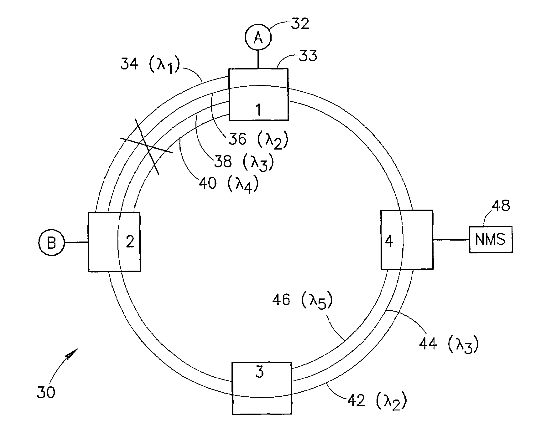
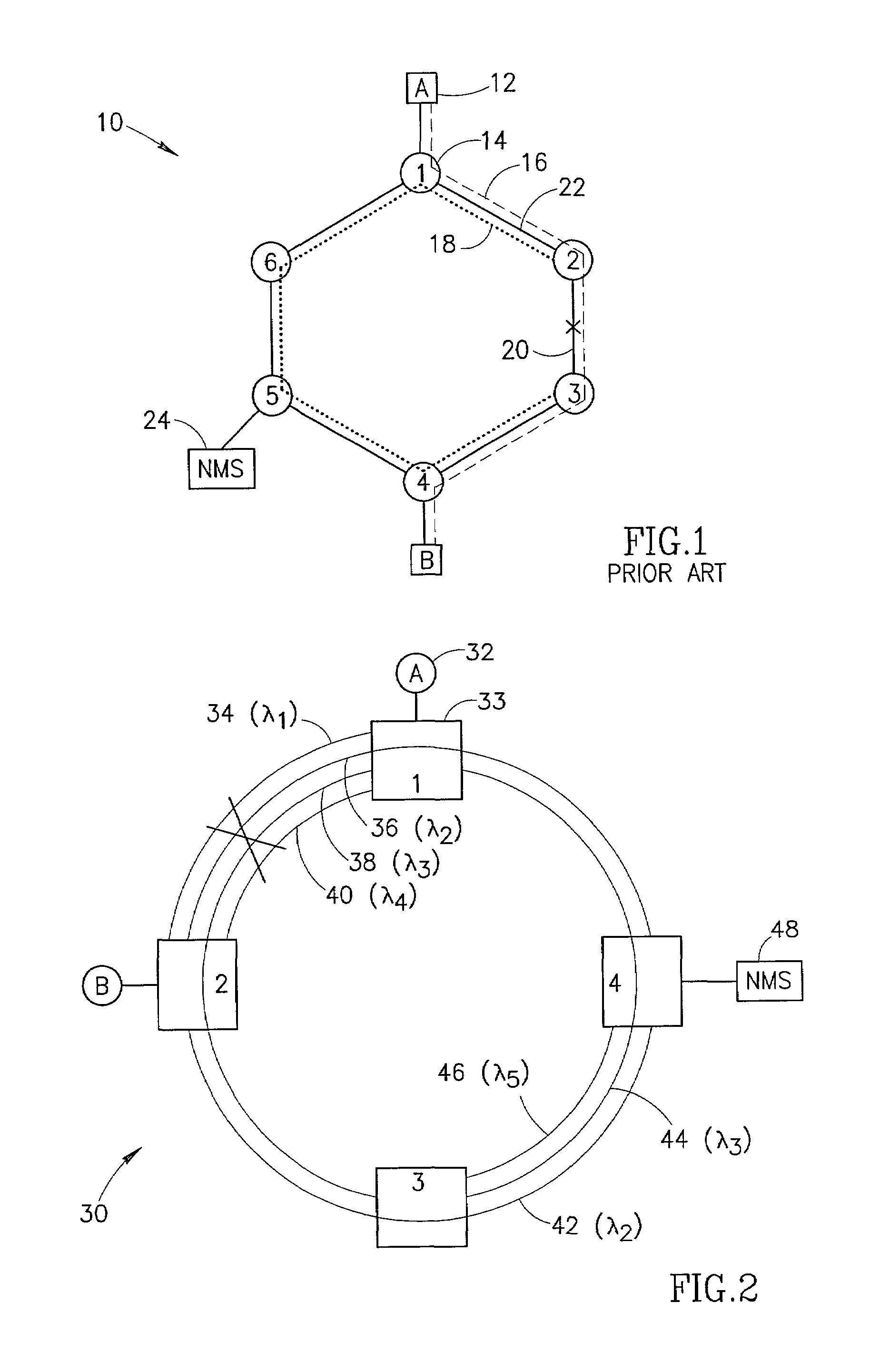
[0058]The first embodiment is described with reference to a network diagram illustrating an example restoration scenario in a ring optical network employing wavelength division multiplexing as shown in FIG. 2. The network, generally referenced 30, comprises a plurality of nodes 33, labeled 1 through 4, end stations 32, labeled A and B and Network Management System (NMS) 48. The nodes are connected to each other via physical fiber links (not explicitly shown).

[0059]The physical links in the network comprise optical fiber using WDM or DWDM wherein multiple colors share the same fiber. Thus, each physical link may comprise a plurality of logical links, each associated with a different color. The use of WDM enables a number of logical links to be established between various nodes in the network. Each logical link may traverse multiple physical links. Each node comprises an Optical Add Drop Multiplexer (OADM) or any other WDM or DWDM devices adapted to ...

second embodiment -

Second Embodiment-Assignment of Virtual Colors

[0077]In the second embodiment of the invention, virtual colors are assigned in order to handle the case where the network does not have sufficient redundancy for protection paths or in the case where fiber bundles are used. A network diagram illustrating an example optical network including WDM segments and non-WDM segments is shown in FIG. 5.

[0078]In the example shown, generally referenced 60, nodes 62 are connected by WDM and non-WDM links. Each node comprises an Optical Add Drop Multiplexer (OADM) adapted to add and drop zero or more colors or to pass zero or more colors through without adding or dropping them. A NMS 72 is connected to the network and implements the mechanism of the present invention. Logical link 64 (dashed line) and logical link 66 (dotted line) are WDM links connecting nodes 1 and 3. Two fibers 68, 70 connect nodes 2 and 3 that are not WDM links, thus they each run a single color.

[0079]Initially, in this example n...


PUM

PropertyMeasurementUnit
switchover timeaaaaaaaaaa
coloraaaaaaaaaa
physical coloraaaaaaaaaa

Abstract

A link based network protection path calculation mechanism wherein a protection route is calculated that is guaranteed not to traverse the link it is intended to protect. The mechanism takes advantage of the fact that the same color cannot pass twice through the same optical fiber. The protection path is determined by eliminating all colors from the logical topology of the network except for the color corresponding to the link to be protected before executing the search algorithm. This serves to guarantee that the protection path calculated will not traverse the same physical fiber as the link to be protected. Virtual colors can be assigned to the links running through fiber bundles such that they do not pass through the same fiber / bundle twice.

Description

FIELD OF THE INVENTION[0001]The present invention relates generally to data communications and more particularly relates to a link level network protection path calculation mechanism for use in optical fiber based networks.BACKGROUND OF THE INVENTION[0002]Currently, the number of data networks and the volume of traffic these networks carry are increasing at an ever increasing rate. The network devices making up these networks generally consist of specialized hardware designed to move data at very high speeds. Typical asynchronous packet based networks, such as Ethernet or MPLS based networks, are mainly comprised of end stations, hubs, switches, routers, bridges and gateways. A network management system (NMS) is typically employed to provision, administer and maintain the network.[0003]It is common for many networks to provide some form of protection in the event of failure. For example, in the event of a link or node failure, the network can be adapted to switch data traffic around...

Claims


Application Information

Patent Timeline
Patent Type & Authority Patents(United States)
IPC IPC(8): G02F1/00
CPCH04J14/0227H04J14/0293H04J14/0246H04J14/0283H04J14/0284H04J14/0295
Inventor OFEK, RONENSHABTAY, LIOR
Owner VENTURE LENDING & LEASING III
Why Eureka
Try Eureka