Soil stabilizer with track apparatus

a technology track apparatus, which is applied in the direction of rider propulsion, applications, roads, etc., can solve the problems of affecting ruts which affect the wheels of soil stabilizing vehicle, and the underlying earth to undergo extreme compression, so as to reduce the compaction of the earth, improve the effect of traction and reduce the effect of ruts

Active Publication Date: 2007-01-02
ATI TECH INC
View PDF19 Cites 27 Cited by
  • Summary
  • Abstract
  • Description
  • Claims
  • Application Information

AI Technical Summary

Benefits of technology

[0010]Another object of the invention is to provide a soil stabilizer which eliminates or reduces vibration and / or bouncing.
[0019]Another object of the invention is to provide a soil stabilizer with a track apparatus which provides improved performance.

Problems solved by technology

Often, the surface upon which a structure will be constructed has insufficient stability such that it will collapse during construction or sometime thereafter.
Such treatment usually dries the ground and makes it sufficiently hard to serve as a base for construction.
Such weight causes the underlying earth to undergo extreme compression.
Such differences in compression can cause ruts which impact the wheels of the soil stabilizing vehicles.
Under these circumstances, the depth of a cut cannot be guaranteed by making a single pass over an area of ground.
Such treatment is not efficient use of labor, materials or fuel.
Furthermore, soil stabilizers often encounter difficult conditions in which traction is poor and the bottom edge encounters substantial resistance.
In such conditions, the stabilizer operator may not be able to get the stabilizer to move forward to make the desired cut.
Such wiggling frequently causes the stabilizer to bounce which further impairs the ability to obtain a cut and soil treatment at the appropriate depth.
Of course, treatment at a shallower depth may not provide sufficient soil stability and may lead to construction problems.
Another problem is frequently encountered by soil stabilizers which are used on hill sides or other uneven terrain, typically in cases where the soil treatment is intended to control movement of water.
Often soil stabilizers employed in such use slide down the hillside or even roll over during operation.
Sliding is typically caused by the poor traction of the soil stabilizer's wheels.
Rolling over usually occurs when the uphill wheel of the soil stabilizer encounters a bump or rut which causes the uphill tire to bounce.
The upward shift in weight causes the center of gravity to shift upward and results in the soil stabilizer rolling over.
Another problem faced by soil stabilizers is the compaction of earth under the soil stabilizer wheels in the direction of travel.
This problem is aggravated when working in wet areas where a soil stabilizer may sink into the earth on its first pass across a path, resulting in a large delay in completing the job.
As can be seen, regardless of the type of soil stabilizer utilized, several problems are encountered when removing and treating large amounts of earth.

Method used


Image

  • Soil stabilizer with track apparatus
  • Soil stabilizer with track apparatus
  • Soil stabilizer with track apparatus

Examples


Embodiment Construction

[0054]Prior track apparatus for vehicles are disclosed in U.S. Pat. No. Re 36,284 (Kelderman), U.S. Pat. No. 5,829,848 (Kelderman), U.S. Pat. No. 6,536,854 (Kahle et al.), U.S. Pat. No. 6,543,861 (Kahle et al.), U.S. Pat. No. 6,543,862 (Kahle et al.) U.S. Pat. No. and 6,557,953 (Kahle et al.), assigned to the assignee of the present invention, and are incorporated herein by reference.

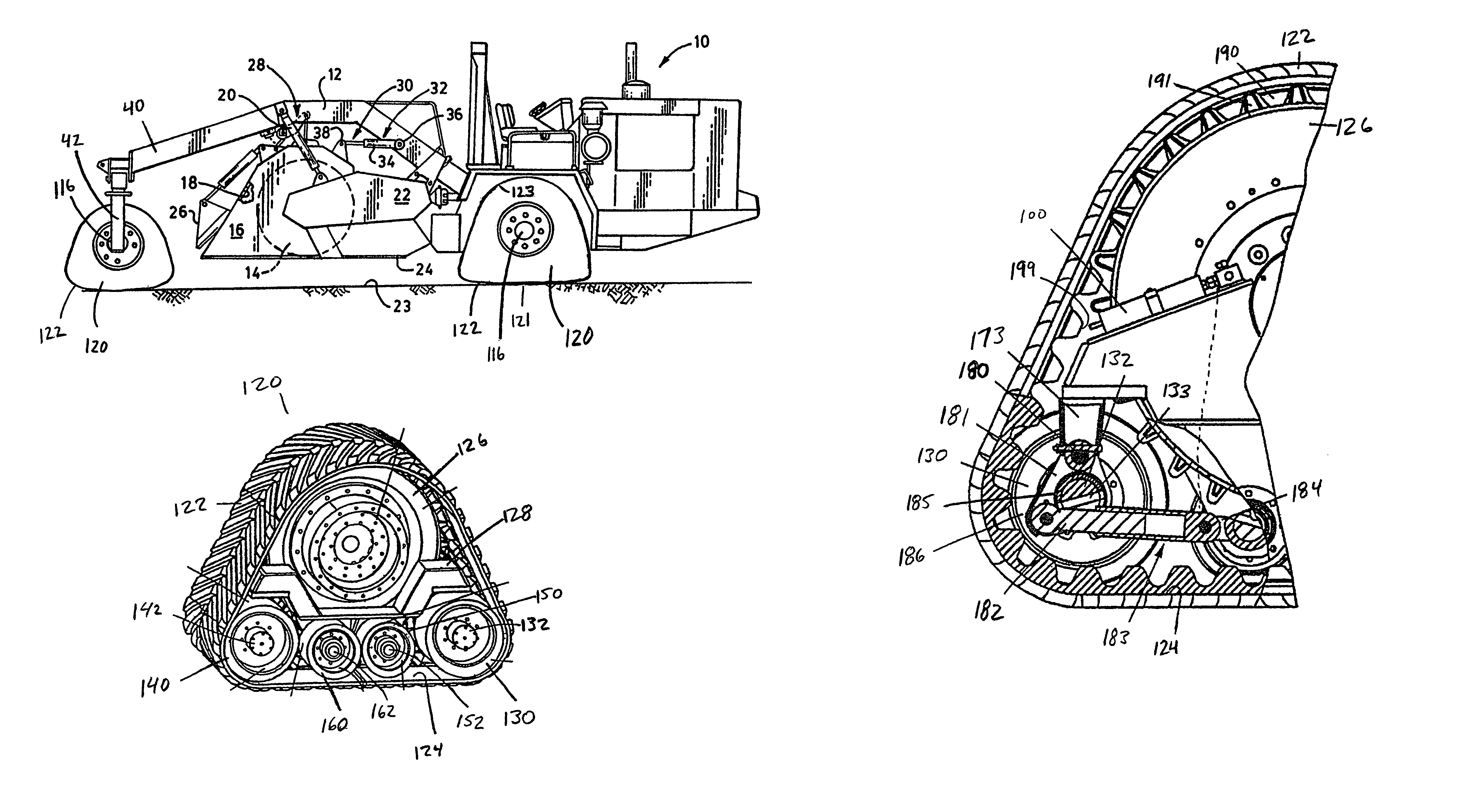
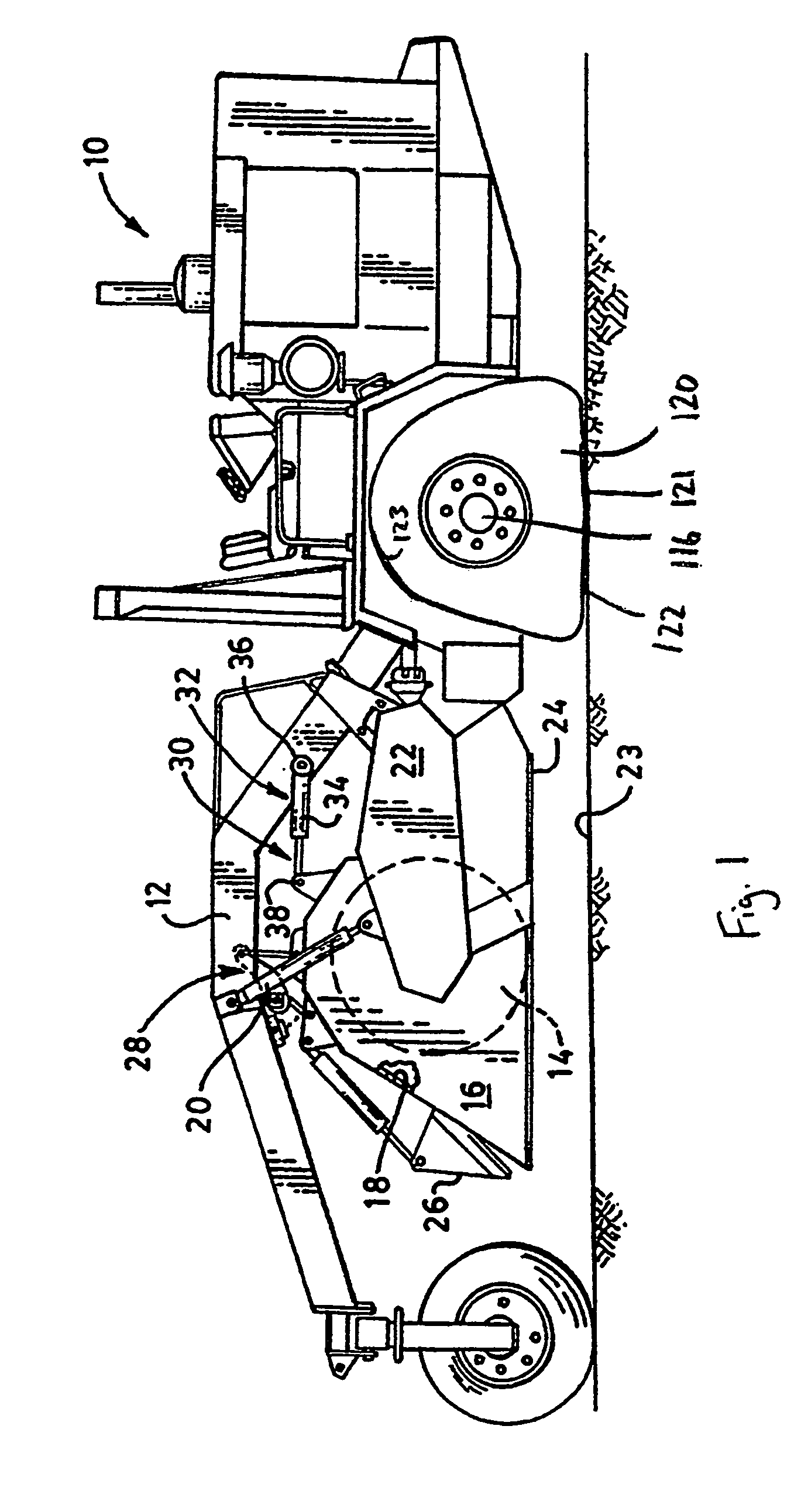
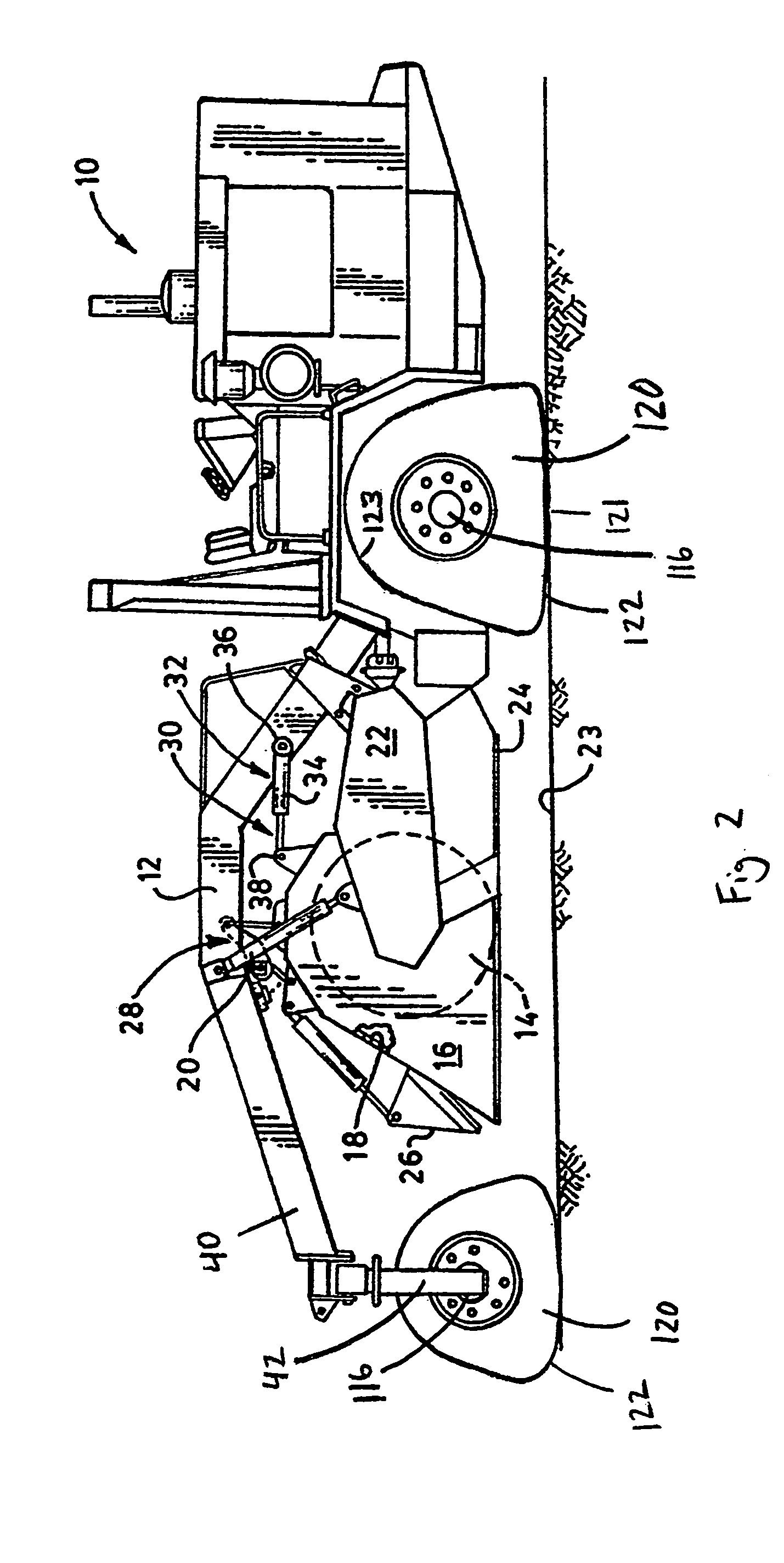
[0055]Referring to FIG. 1, a soil stabilizer in accordance with the present invention is generally designated by the reference numeral 10. Soil stabilizer 10 includes a frame 12, a horizontally disposed and vertically adjustable rotor 14 having ground engaging tools mounted thereon, and a hood member 16 that forms an open bottom mixing chamber 18 about the rotor 14.

[0056]A pair of hydraulic lift cylinders 20, disposed on opposed sides of the hood member 16, connect a pair of similarly disposed rotor drive cases 22 to the frame 12 and controllably position the rotor 14 vertically with respect to a ground...


PUM


Abstract

A soil stabilizer treating earth includes a stabilizer frame, a rotor rotatably mounted thereon and including a cutting tool for cutting earth and being movable such that the rotor may engage various depths of earth, a rotatable axle, and a track apparatus mounted on the rotatable axle, the track apparatus supporting the stabilizer frame and providing for movement of the stabilizer frame and rotor across the ground surface. The track apparatus may include a continuous flexible track having an upper length and a ground-engaging lower length and including an inner surface, an axle wheel mountable to the rotatable axle for rotational movement therewith, the axle wheel engaging the inner surface of the flexible track along the upper length to drive the flexible track in response to rotation of the axle, and an apparatus frame for mounting the axle wheel.

Description

FIELD OF THE INVENTION[0001]This invention relates generally to earth working equipment. More specifically, the invention pertains to soil stabilizing devices used to treat soil to either improve stability of subsurface layers of earth, control movement of subsurface water or both.BACKGROUND OF THE INVENTION[0002]In the construction industry, the need for manipulating soil and other bases for construction is frequently encountered. This need typically occurs in the construction of buildings, paved roads and parking lots and other improvements. Often, the surface upon which a structure will be constructed has insufficient stability such that it will collapse during construction or sometime thereafter. In order to strengthen the ground surface, the ground surface is treated with lime, concrete or other additives. Such treatment is typically performed at a depth of sixteen inches from the ground surface. If the ground is wet, the earth typically requires multiple treatments at four inc...

Claims


Application Information

Patent Timeline
Patent Type & Authority Patents(United States)
IPC IPC(8): A01B51/00A01B5/00E01C21/00E02F5/10E02F9/02
CPCE01C21/00E02F9/02E02F5/08
Inventor JUNCKER, KENNETH J.
Owner ATI TECH INC
Why Eureka
Try Eureka