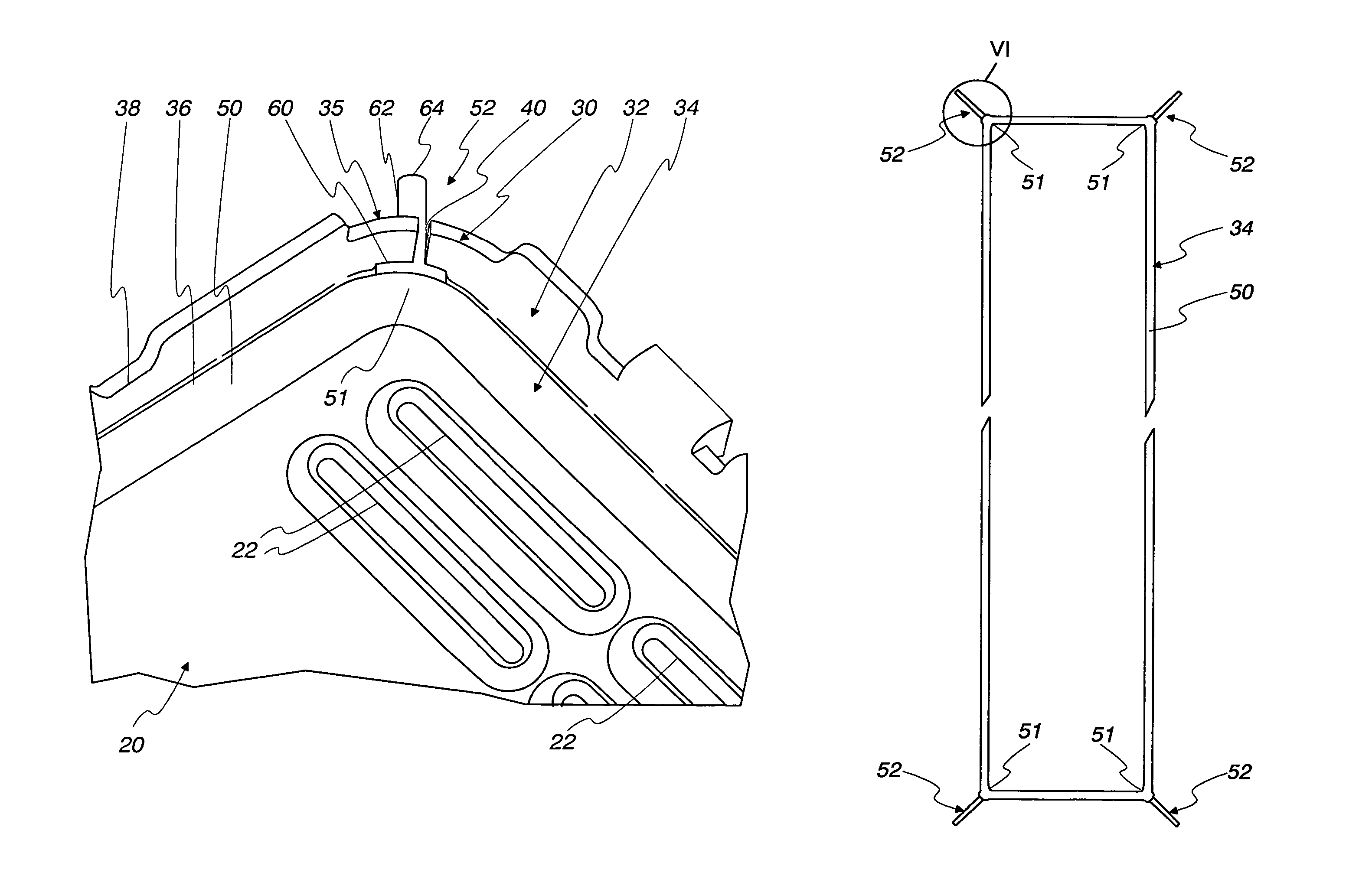
Elastomeric gasket in gasket well of heat exchanger

a technology of heat exchanger and gasket well, which is applied in the field of gaskets or seals, can solve the problems of often unreliable approach

Inactive Publication Date: 2007-01-02
MODINE MFG CO
View PDF31 Cites 23 Cited by
  • Summary
  • Abstract
  • Description
  • Claims
  • Application Information

AI Technical Summary

Benefits of technology

[0011]In one feature of the invention, a gasket well / gasket combination is provided for use with a mating part to form a sealed connection. The combination includes a gasket well defined by a base wall and a side wall extending upward from the base wall, the side wall including an upwardly opening slot having a slot width SW. The combination further includes an elastomeric gasket shaped to be received in the gasket well and compressed between the base wall and the mating part to form the sealed connection. The gasket includes a locating feature having a shoulder portion and a tab extending outwardly from the shoulder portion to a terminal end of the tab. The tab has a transverse width that does not increase from the shoulder portion to the terminal end, with the transverse width being larger than the slot width SW with the tab in an undeformed state. The gasket is receivable in the gasket well with the tab pinched in the slot and the shoulder portion abutted against the side wall adjacent the slot to properly locate the gasket within the gasket well.

Problems solved by technology

One problem associated with such constructions is the failure mode sometimes referred to as gasket-out-of-well (GOW), wherein the gasket is not located properly in its receiving well and ultimately fails to seal the associated joint, thereby resulting in a leak.
Often this condition occurs because the gasket rides up on an inner wall of the receiving well due to a short gasket condition and is visually undetectable in the assembled state of the tank / header assembly.
However, this approach is often not reliable.

Method used


Image

  • Elastomeric gasket in gasket well of heat exchanger
  • Elastomeric gasket in gasket well of heat exchanger
  • Elastomeric gasket in gasket well of heat exchanger

Examples


Embodiment Construction

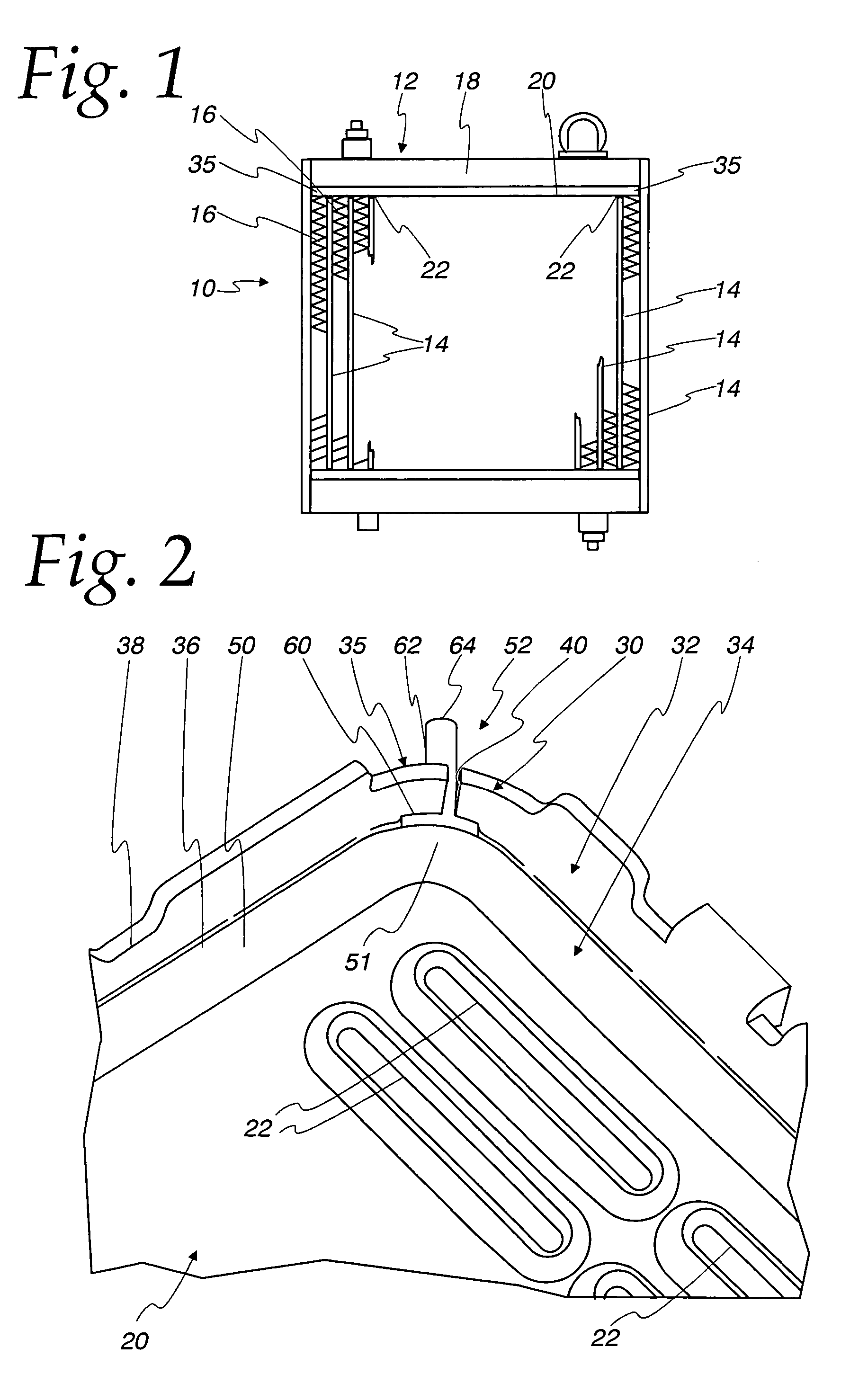
[0024]With reference to FIG. 1, a heat exchanger 10 is shown and includes a header / tank assembly 12 that collects and / or distributes a working fluid to the interior of a plurality of heat exchanger tubes 14 that transfer heat to a second fluid flowing through fins 16 extending between the tubes 14. The assembly 12 includes a tank 18 and a rectangular-shaped header plate 20 that includes a plurality of tubes slots 22 that sealingly receive the ends of the tubes 14. It should be appreciated that while the gasket well / gasket combinations embodying the present invention are described herein in connection with use in the heat exchanger 10 and are particularly useful in such constructions, combinations embodying the present invention may find use in many other applications requiring a sealed joint, including non-heat exchanger applications and heat exchanger applications other than the heat exchanger construction 10 shown in FIG. 1. Accordingly, no limitation to use with a heat exchanger ...


PUM


Abstract

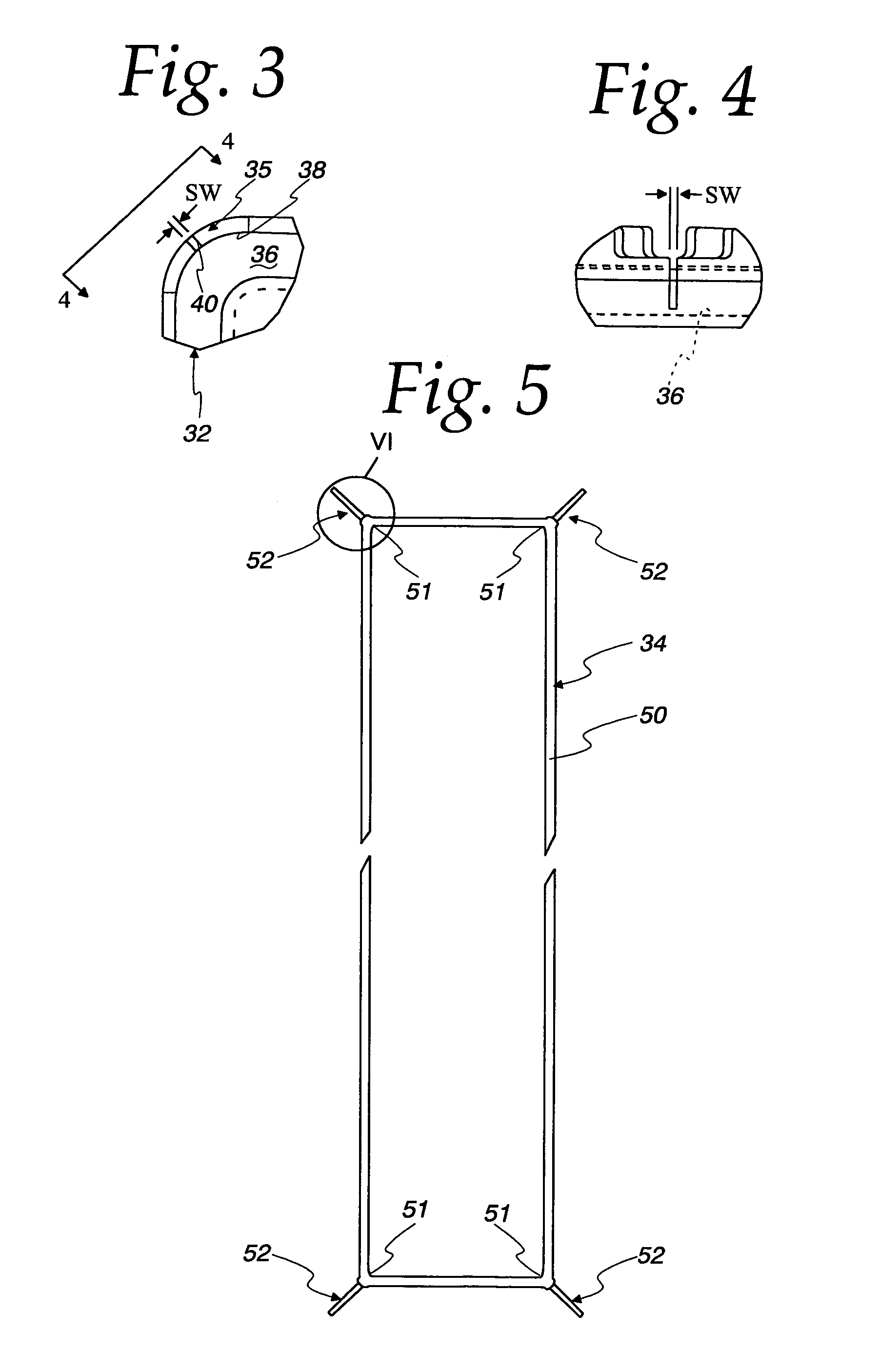
A gasket well / gasket combination (30) is provided, and may be particularly useful for use in a header / tank assembly (12) for a heat exchanger (10). The combination (30) includes a gasket well (32) defined by a base wall (36) and a side wall (38) extending upwardly from the base wall (36), with the side wall (38) including an upwardly opening slot (40) having a width (SW). The combination further includes an elastomeric gasket (34) shaped to be received in the gasket well (32) and compressed between the base wall (36) and a mating part to form a sealed connection. The gasket (34) includes a seal bead (50) and a locating feature (52) having a tab (62) extending outwardly from the seal bead (50) to a terminal end (64) of the tab (62), with the tab (62) having a transverse width that does not increase from the seal bead (50) to the terminal end (64). The transverse width is larger than the slot width (SW) with the tab (62) in an undeformed state. The gasket (34) is receivable in the gasket well (32) with the tab (62) pinched in the slot (40) across the transverse width to retain the gasket (34) in the gasket well (32).

Description

FIELD OF THE INVENTION[0001]This invention is directed generally to gaskets or seals and their associated gasket or seal channel, groove or well, and in more particular applications, to such structures as used in a header / tank assembly for a heat exchanger.BACKGROUND OF THE INVENTION[0002]It is common in certain heat exchanger constructions, such as radiators, to provide a header / tank assembly wherein an elastomeric seal or gasket is located in a receiving groove, channel or well in the header plate and then compressed between the header plate and the tank to seal the joint therebetween. One problem associated with such constructions is the failure mode sometimes referred to as gasket-out-of-well (GOW), wherein the gasket is not located properly in its receiving well and ultimately fails to seal the associated joint, thereby resulting in a leak. Often this condition occurs because the gasket rides up on an inner wall of the receiving well due to a short gasket condition and is visua...

Claims


Application Information

Patent Timeline
Patent Type & Authority Patents(United States)
IPC IPC(8): F16J15/02
CPCF28F9/0226F28F9/165F28F2230/00
Inventor MERKLEIN, BRIAN A.ANDERS, JOSEPH P.
Owner MODINE MFG CO
Why Eureka
Try Eureka