Adjusting settings of an I/O circuit for process, voltage, and/or temperature variations

a technology of adjusting the settings of an i/o circuit and process, applied in the direction of voltage/temperature variation compensation, oscillation generator, reliability increasing modifications, etc., can solve the problem of not providing functionality for testing or observing the pvt settings, or for controlling the pvt of the output driver

Inactive Publication Date: 2007-01-02
AVAGO TECH INT SALES PTE LTD
View PDF13 Cites 16 Cited by
  • Summary
  • Abstract
  • Description
  • Claims
  • Application Information

AI Technical Summary

Benefits of technology

[0007]In the prior art system 100 of FIG. 1, the PVT sensing circuit 102 provides control signals to the output driver 104, and disadvantageously, the system 100 contains no control logic to permit selectively bypassing or adjusting the control signal from the PVT sensing circuit 102 under certain circumstances, e.g., to compensate for loads having varying impedances. Moreover, no functionality is provided for testing or observing the PVT settings, or for controlling the PVT of the output driver 104 through software. Such control logic could permit selection between (1) control signals provided by the PVT sensing circuit and (2) control signals stored in a hardware register. Additionally, control logic could (i) provide the capability to offset the selected control signal by a fixed amount and (ii) select whether or not the offset is applied. Moreover, having logic control could permit full testability and observability of the selected control signal, an offset value applied thereto, and the resulting output signal.
[0008]In certain embodiments, the present invention provides a control circuit and method for controlling the PVT settings of an VO circuit, such as an output driver, whereby a PVT controller having appropriate control logic is provided so as to permit PVT compensation to be observed, tested, and selectively adjusted. The PVT controller permits selection between control signals provided by a PVT sensing circuit and control signals stored in a hardware register. The PVT controller further (1) provides the capabilities to offset the selected control signal by a fixed amount and select whether or not the offset is applied and (2) permits full testability and observability of the selected control signal, an offset value applied thereto, and the resulting output signal.

Problems solved by technology

Moreover, no functionality is provided for testing or observing the PVT settings, or for controlling the PVT of the output driver 104 through software.

Method used


Image

  • Adjusting settings of an I/O circuit for process, voltage, and/or temperature variations
  • Adjusting settings of an I/O circuit for process, voltage, and/or temperature variations
  • Adjusting settings of an I/O circuit for process, voltage, and/or temperature variations

Examples


Embodiment Construction

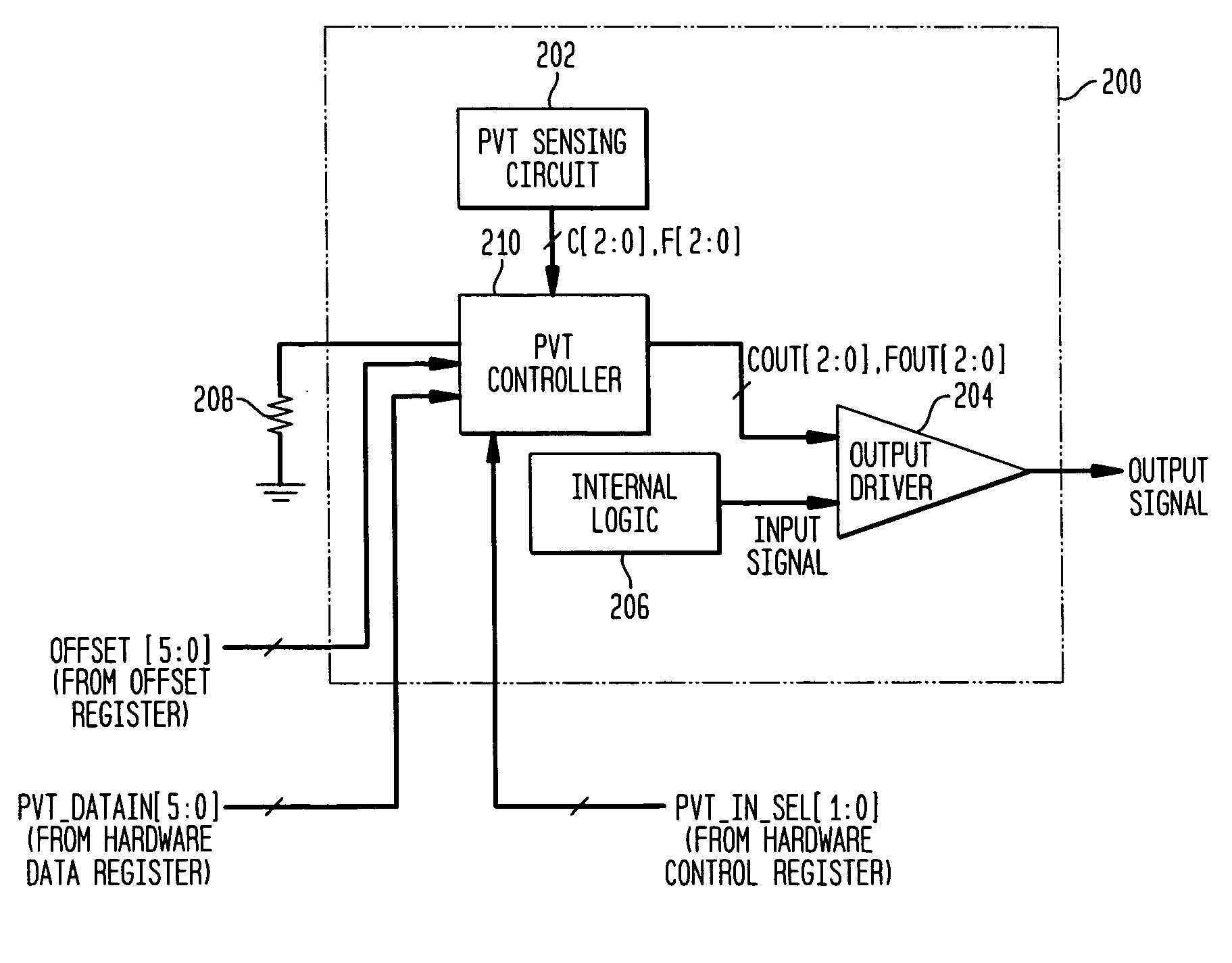
[0019]In accordance with exemplary embodiments of the present invention, a PVT controller having appropriate control logic is provided so as to permit PVT compensation to be observed, tested, and selectively adjusted. The PVT controller permits selection between PVT sensing circuit-provided control signals and control signals stored in a hardware register, provides the capability to offset the selected control signal by a fixed amount and select whether or not the offset is applied, and permits full testability and observability of the selected control signal, an offset value applied thereto, and the resulting output signal.

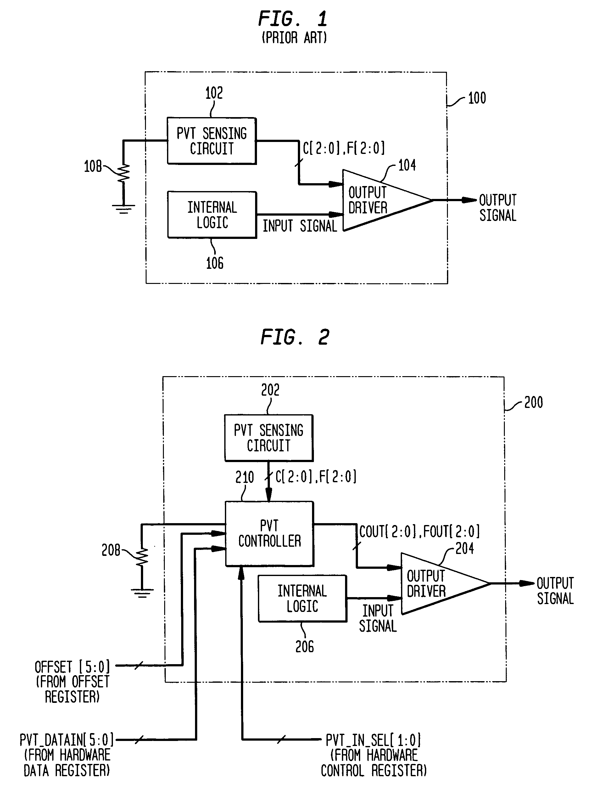
[0020]With reference first to FIG. 2, a block diagram of an exemplary output driver system 200 consistent with the invention is illustrated. As shown, the output driver system 200 includes internal logic 206, an output driver 204, a PVT sensing circuit 202, and a PVT controller 210. The internal logic 206 provides an input signal to the output driver 204, which, ...


PUM


Abstract

A control circuit and method for controlling the electrical characteristics of an input / output (I / O) circuit such as an output driver to account for variations in fabrication process, supply voltage, and / or temperature (PVT) conditions includes a PVT controller having appropriate control logic to permit PVT compensation to be observed, tested, and selectively adjusted. The PVT controller permits selection between PVT sensing circuit-provided control signals and control signals stored in a hardware register for controlling drive strength. The PVT controller further provides the capability to offset the selected drive strength by a fixed amount and select whether or not the offset is applied and permits full testability and observability of the selected control signal, an offset value applied thereto, and the resulting output signal.

Description

BACKGROUND OF THE INVENTION[0001]1. Technical Field[0002]The present invention relates generally to controlling electrical characteristics associated with input / output (I / O) circuits, and more particularly, to observing, testing, and adjusting the settings of an I / O circuit such as an output driver to account for variations in fabrication process, supply voltage, and / or temperature (PVT) conditions.[0003]2. Prior Art[0004]I / O circuits are used to interface traditional circuitry such as integrated circuits (ICs) with electrical environments external to the IC. An I / O circuit acts as a driver for signals generated by the IC and provides these signals to a pad, which, in turn, interfaces with the external electrical environment. In addition or alternatively, an I / O circuit may receive signals from the external electrical environment through the pad. A critical challenge in the design, fabrication, and operation of these I / O circuits is that their electrical characteristics, e.g., imped...

Claims


Application Information

Patent Timeline
Patent Type & Authority Patents(United States)
IPC IPC(8): H03K19/003
CPCH03K19/00369
Inventor EL-KIK, TONY S.SEAMAN, ANTHONY W.SIEGEL, STEFAN A.
Owner AVAGO TECH INT SALES PTE LTD
Why Eureka
Try Eureka