Rotary cleaning body, suction port body of vacuum cleaner, and production method of rotary cleaning body

a technology of axial member and production method, which is applied in the direction of carpet cleaner, vehicle cleaning, bowling games, etc., to achieve the effect of ensuring sufficient precision of axial member and preventing uneven rotation

Inactive Publication Date: 2007-01-09
TOSHIBA TEC KK
View PDF13 Cites 55 Cited by
  • Summary
  • Abstract
  • Description
  • Claims
  • Application Information

AI Technical Summary

Benefits of technology

[0008]The present invention calls for securing the base ends of cleaning members in recess-shaped, axially extending receiving grooves that are formed in the cylindrical outer surface of a mounting member having a cylindrical shape, thereby attaching the cleaning members to the mounting member so that the cleaning members extend along the axial direction and protrude outward in the radial direction of the mounting member, and, subsequently, inserting an axial member through the center of the mounting member and attaching the mounting member to the axial member so that each receiving groove is shaped into a spiral. As the formation process of the axial member does not involve twisting of the axial member, a sufficient precision of the axial member is ensured. Therefore, when the rotary cleaning body is rotated, uneven rotation is prevented.

Problems solved by technology

This feature presents a problem in that it is prone to distortion and therefore difficult to ensure sufficient precision, often resulting in uneven rotation when the shaft is rotated.

Method used


Image

  • Rotary cleaning body, suction port body of vacuum cleaner, and production method of rotary cleaning body
  • Rotary cleaning body, suction port body of vacuum cleaner, and production method of rotary cleaning body
  • Rotary cleaning body, suction port body of vacuum cleaner, and production method of rotary cleaning body

Examples


Embodiment Construction

[0017]Next, the structure of a vacuum cleaner according to another embodiment of the present invention is explained hereunder, referring to relevant drawings.

[0018]Referring to FIG. 7, numeral 1 denotes the main body of the cleaner. The cleaner main body 1 incorporates a motor fan 2. The cleaner is an electric vacuum cleaner that is adapted to suction up dust together with suction air generated by driving the motor fan 2 and collect the suctioned dust into a dust collection pack (not shown).

[0019]The cleaner main body 1 has a lower casing 3, which is made of synthetic resin and open at the top. Provided on top of the lower casing 3 is an upper casing 4 provided with an open / close cover that is made of synthetic resin and serves to open or close a part of the top of the lower casing 3. The lower casing 3 and the upper casing 4 together constitute a main body casing 5, which serves as the casing referred to, for example, the Summary of the Invention.

[0020]A rotating wheel (not shown) ...


PUM


Abstract

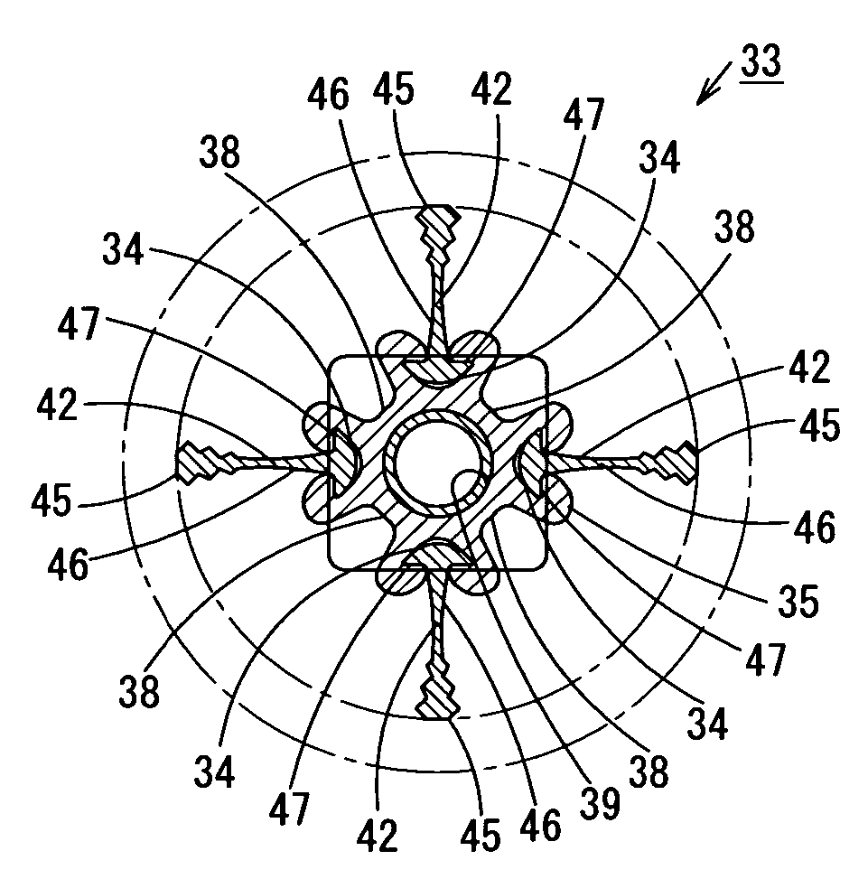
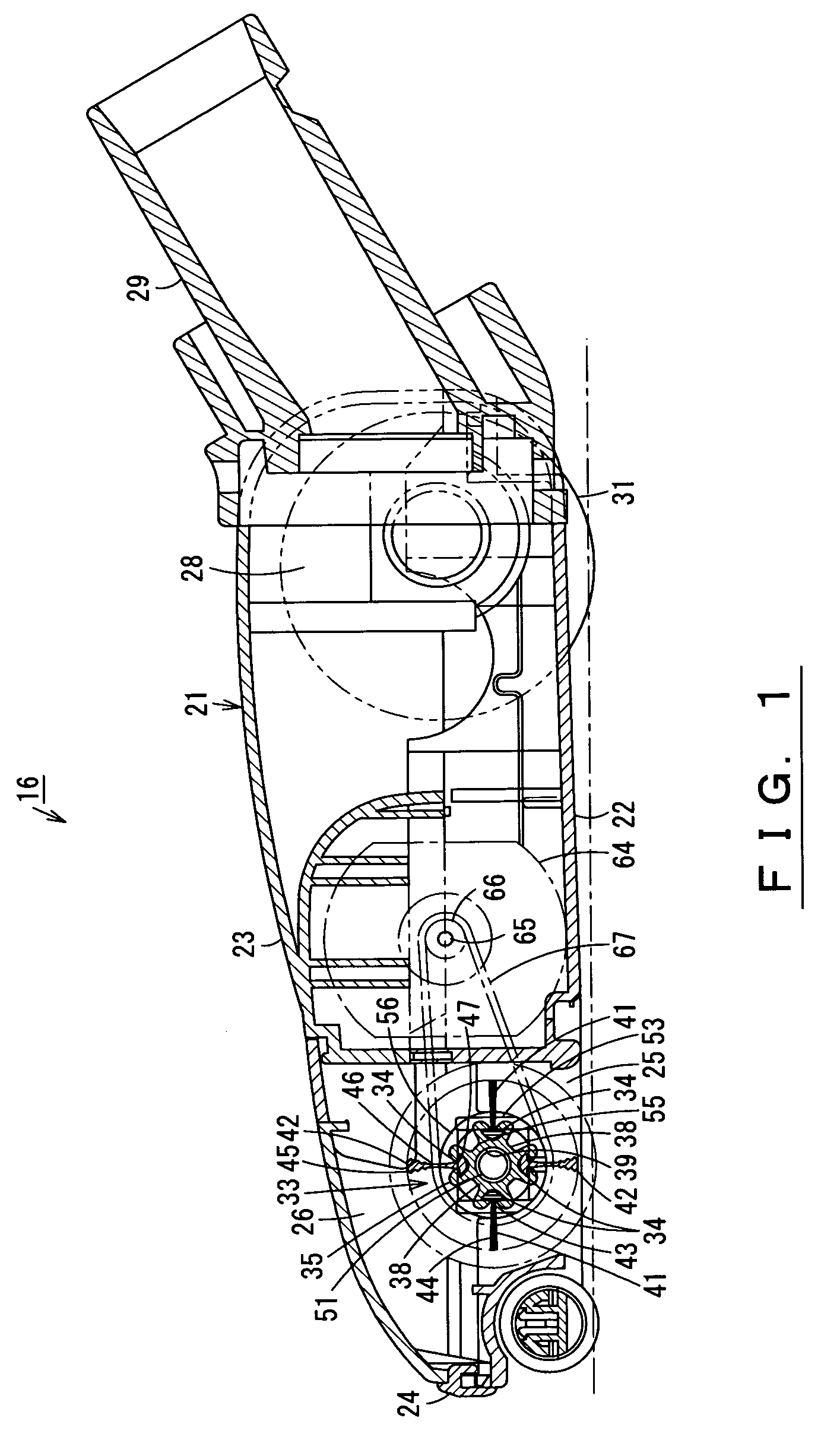
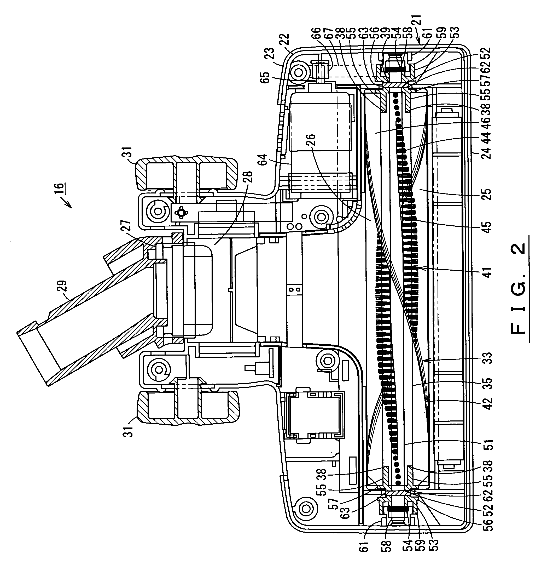
Catching grooves (34) extending in the axial direction are formed in the cylindrical outer surface of a brush base (35) that has a slender, substantially cylindrical shape and made of a twistable material. Brush attaching portions (43) of brush members (41) and blade attaching portions (47) of scraping members (42) are respectively secured in the catching grooves (34) so that axially aligned bristles (44) of each brush member (41) and an axially extending blade (46) of each scraping member (42) project from the cylindrical outer surface of the brush base (35). Receiving members (53) are respectively fitted to both ends of a shaft (51) inserted through a shaft insertion hole (39) of the brush base (35). By rotating the receiving members (53) in opposite directions, the brush base (35) is twisted in a spiral and secured. By eliminating the necessity of forming the brush base (35) in a twisted shape beforehand by means of twist extrusion molding, the invention facilitates production of the brush base (35). Adjusting the degree of twisting the brush base (35) ensures a sufficient twisting precision.

Description

[0001]This application is a Continuation Application of International Application No. PCT / JP2003 / 014894 filed Nov. 21, 2003, which claims the priority of Japanese Application No. 2002-340017 filed Nov. 22, 2002.TECHNICAL FIELD[0002]The present invention relates to a rotary cleaning body, a suction port body of a vacuum cleaner equipped with the rotary cleaning body, and a production method of the rotary cleaning body, wherein cleaning members that extend in a spiral along the axial direction and protrude outward are attached to the cylindrical outer surface of an axial member of the rotary cleaning body.BACKGROUND ART[0003]One of conventionally known examples of rotary cleaning bodies of this type is disclosed in Japanese Examined Patent Publication No. 6-85752. The rotary cleaning body described in Japanese Examined Patent Publication No. 6-85752 is provided with a shaft that is in a slender, cylindrical shape having a plurality of catching grooves formed in the cylindrical outer s...

Claims


Application Information

Patent Timeline
Patent Type & Authority Patents(United States)
IPC IPC(8): A47L9/04A46B9/08
CPCA47L9/0477A47L9/04
Inventor OMOTO, SHUHEIOHTSU, YASUHIRO
Owner TOSHIBA TEC KK
Why Eureka
Try Eureka