
Unit and method for recycling a bituminous membrane

a technology of a bituminous membrane and a recycling unit, which is applied in the direction of grain treatment, applications, and ways, can solve the problems of premature wear of the rotor, the inability to use recycled materials as quality raw materials, and the complexity of the bituminous membrane recycling, so as to improve the quality of the recycled material, the unit is simple and less expensive, and the reinforcement present in the membrane is disintegrated. , the effect of reducing the cost of the uni

Active Publication Date: 2007-01-09
IMPERBEL
View PDF4 Cites 6 Cited by
  • Summary
  • Abstract
  • Description
  • Claims
  • Application Information

AI Technical Summary

Benefits of technology

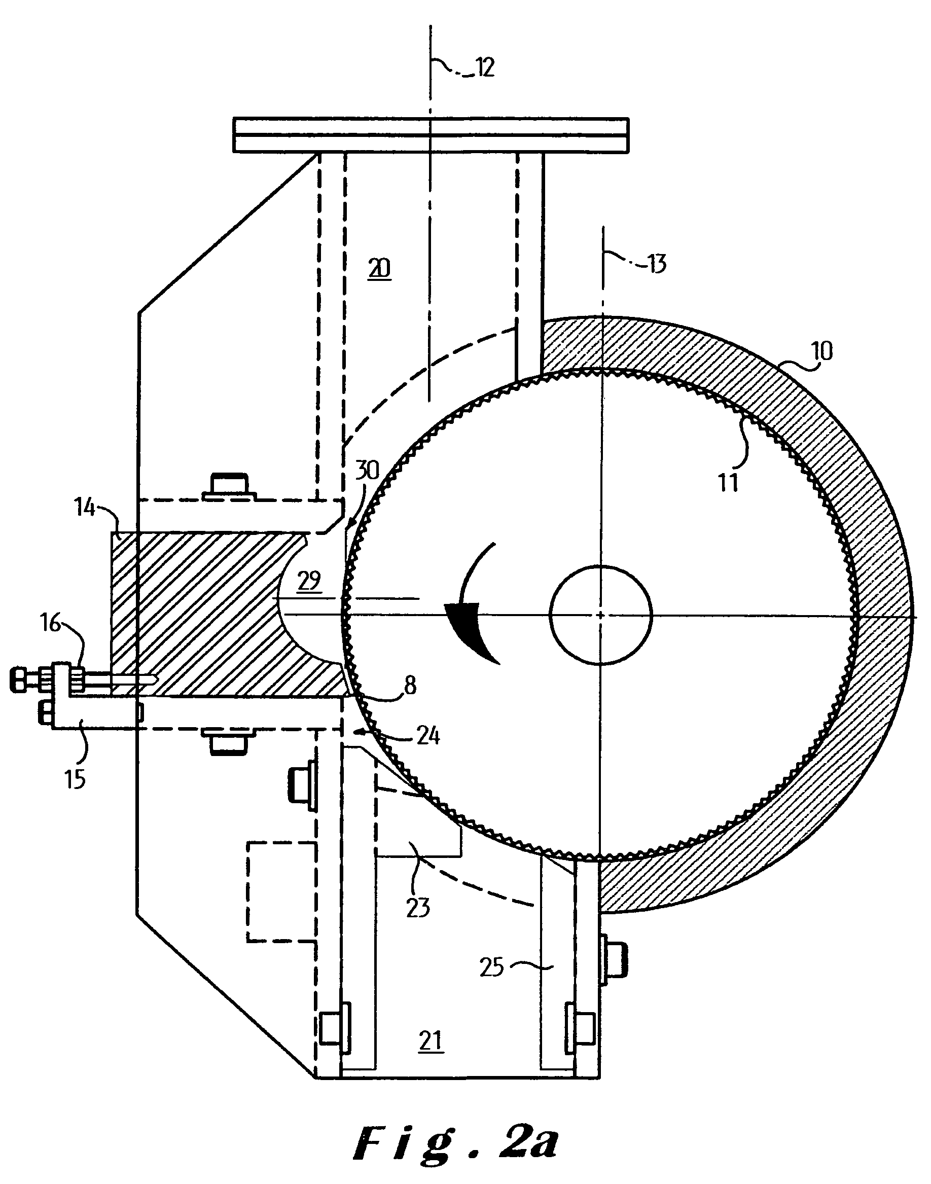
"The invention is a recycling unit that is designed to recycle bituminous membrane. The unit includes a trituration chamber that can adjust its size and shape. A scraper is also included to clean the rotor. The scraper has a stepped profile to distinguish between fully triturated material and insufficiently triturated material. The bituminous binder can be melted and recovered for recycling, and the recycled material can be used as a raw material for various applications. The recycling unit is efficient, cost-effective, and can adapt to different types of membrane. Additionally, the invention provides a solution to the problem of mineral covering on the membrane, which can cause premature wear of the rotor and lead to insufficiently triturated material. The recycling unit has a suction effect and a pivoted scraper to improve the passage of the material through the unit. The invention also includes a counter-element with a knife blade to pulverize the mineral covering on the rotor."

Problems solved by technology

The recycling of a bituminous membrane is also made more complicated when the latter is provided on the surface with a mineral covering such as slate flakes or granules.
This is because these flakes or these granules are insufficiently ground in the known methods and thus remain in the form of large particles in the ground material.
The recycled material thus cannot be used as a quality raw material.
Moreover, the presence of these large particles in the ground material will in its turn lead to premature wear of the rotor.

Method used


Image

  • Unit and method for recycling a bituminous membrane
  • Unit and method for recycling a bituminous membrane
  • Unit and method for recycling a bituminous membrane

Examples


Embodiment Construction

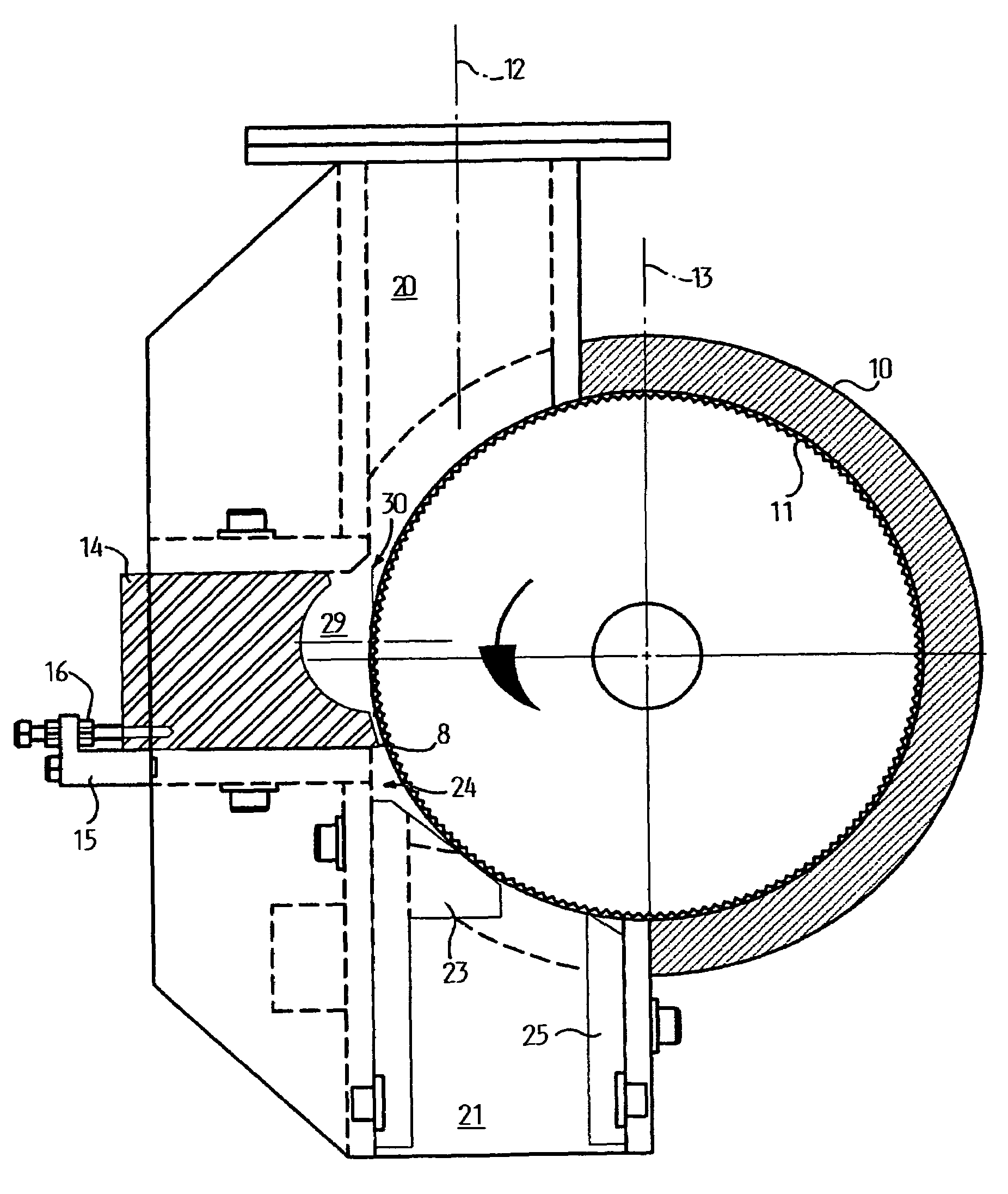
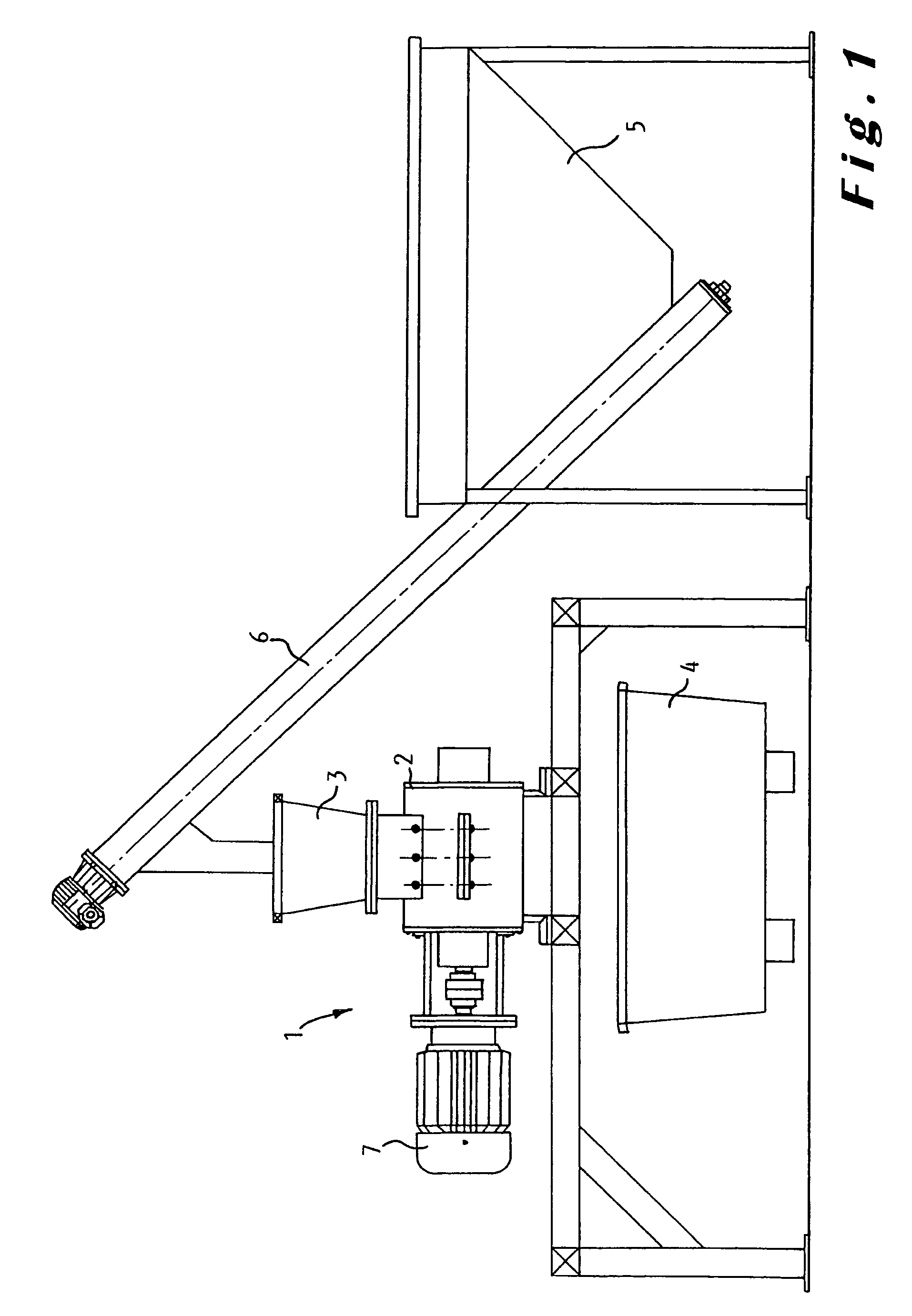
[0031]In the example embodiment illustrated in FIG. 1, the recycling unit 1, according to the invention, comprises a feed hopper 3 connected to the input of a first member 2 provided with a rotor housed in a stator. A motor 7 drives the rotor rotationally. The speed of rotation is for example 100 to 3000 rpm. The output of the first member opens out above a tank 4 in which the viscous substance produced by the first member is recovered.

[0032]To carry out the recycling of the membrane, the latter is first reduced to pieces, for example by cutting up, which are introduced into another feed hopper 5. The prior cutting up of the membrane fragments and pieces depends on the one hand on the size of the membrane fragments and on the other hand on the profile of the rotor at the level of the input of the member. A feed screw having a large and deep screw thread will be better able to process large pieces than a screw with a small thread of reduced depth.

[0033]Membranes are generally provide...


PUM

PropertyMeasurementUnit
distanceaaaaaaaaaa
distanceaaaaaaaaaa
distanceaaaaaaaaaa

Abstract

Method and unit for recycling a bituminous membrane provided with at least one reinforcement, which membrane is reduced to pieces which are introduced into a recycling unit, provided with a first rotor, housed in a first stator, and where they are heated and ground, said pieces being conveyed into a chamber, delimited by an external wall of the first rotor and a recess arranged in a counter-element mounted on the stator, where they are subjected to a trituration, the pieces thus triturated then being discharged from the chamber by flowing along said external wall of the rotor.

Description

CLAIM TO PRIORITY[0001]This application claims priority from PCT / BE2003 / 000116, filed Jun. 30, 2003, which claims priority of Belgian Patent Application No. 2002 / 0418, filed Jun. 28, 2002.BACKGROUND OF THE INVENTION [0002]The present invention concerns a recycling unit organized for recycling a bituminous membrane provided with at least one reinforcement, which unit comprises a first rotor housed in a first stator, provided with a chamber delimited by an external wall of the first rotor.[0003]A recycling unit is known from the patent U.S. Pat. No. 4,185,784. In the known unit, the material to be recycled in introduced into the recycling unit provided with heating means. The material to be recycled thus melts under the effect of the heat and friction with the rotor of the unit. The rotation of the rotor disintegrates the reinforcements present in the material to be recycled so that the product thus obtained is recyclable. The known unit comprises a chamber that is arranged in the wal...

Claims


Application Information

Patent Timeline
Patent Type & Authority Patents(United States)
IPC IPC(8): B02C19/00B02C4/10B02C4/20B02C4/34B02C4/40B02C4/44B29B17/04C10C3/14E01C19/10
CPCB02C4/10B02C4/20B02C4/34B02C4/40B02C4/44E01C19/1004C10C3/14B29B17/04B29B2017/0476B29B2017/0484B29K2095/00Y02W30/52Y02W30/62
Inventor MACALUSO, NINOBERTAND, ERIC
Owner IMPERBEL
Learn More