Apparatus and method for forming internally ribbed or rifled tubes

a technology of internal ribs and rifled tubes, applied in the direction of metal rolling arrangements, drawing mandrels, manufacturing tools, etc., can solve the problems of limited use of internally ribbed tubes, inability to achieve sufficient reduction, and inability to economically produce in commercial quantities, etc., to prolong the tool life, economic and consistent production, and increase productivity

Active Publication Date: 2006-04-04
DOOSAN BABCOCK ENERGY AMERICA
View PDF30 Cites 6 Cited by
  • Summary
  • Abstract
  • Description
  • Claims
  • Application Information

AI Technical Summary

Benefits of technology

[0013]The present invention overcomes the disadvantages of prior apparatus and methods for forming internally helically or spirally ribbed or rifled tubes. The apparatus and method of the present invention increase productivity and prolong tool life in a cold drawing process for forming internal helical or spiral ribs or rifles in tubing. With the present invention, the forces exerted on the plug tool used to form internal helical or spiral ribs or rifles in tubing in a cold drawing process are minimized. The tubing being drawn is squeezed onto the plug as much as the plug tool is forced into the tubing, and minimum force occurs since the width of the grooves in the plug is equal as far as practically possible to the width of the lands between the grooves. The apparatus and method of the present invention allow internally helically or spirally ribbed or rifled tubes to be produced in commercial quantities economically and consistently.
[0014]Heat transfer tubes manufactured in accordance with the present invention have an optimized multiple rib configuration advantageous for use in boilers and offering excellent heat transfer characteristics, operating at low mass flux density, adapting to a vertical tube arrangement, and working effectively in both sub-critical and super-critical pressures. Heat transfer tubes manufactured pursuant to the present invention extend high heat transfer rates by maintaining a high density water film in contact with the heat transfer tubes longer at low mass fluxes and high fluid enthalpies. Heat transfer tubes manufactured pursuant to the present invention may be used in a vertical arrangement in a once-through boiler to provide lower pressure loss, reduced boiler feed pump power requirements, positive flow characteristics to suit variable heat fluxes, lower heat rate through sliding pressure operation resulting in power savings, increased boiler continuous output, reduced furnace temperatures thereby minimizing stresses, smaller tube to tube temperature differences, simpler and less expensive construction due to self-supporting furnace walls, the elimination of valves between the furnace and superheater, the elimination of flow balancing valves, and shorter installation times.

Problems solved by technology

The use of internally ribbed tubes was still limited because the benefit derived from the internally ribbed tubes was not as great in many boiling ranges with certain arrangements and dimensions of the ribs.
To date, however, it has not allowed sufficient reduction to enable a once-through boiler furnace to be cooled successfully in a single vertical pass.
The introduction of “optimized” multi-lead rifled tubing with steeper lead angle and taller rib, as represented by Kastner et al ('194), has finally achieved this goal but the manufacturing difficulties have been such that it could not be economically produced in commercial quantities.
Small lengths of rifled tubing produced for performance testing purposes do not reveal the range of problems associated with the manufacture of rifled tubing in commercial quantities.
Production of internally ribbed tubes pursuant to the Kastner et al. patent presents fabrication problems such as difficulty in removing the rib-forming tool, the presence of stresses that cause frequent tool breakages, and a very slow rate of production.
Many prior apparatus and methods for forming internal helical or spiral ribbing in tubes are associated with drawbacks due to the forces imposed on the plug tool during the drawing process leading to relatively short tool life, relatively low productivity and the inability to economically and consistently produce internally helically or spirally ribbed tubes in commercial quantities.
Internally helically or spirally ribbed tubes produced using prior apparatus and methods may present deficiencies when used in a vertical arrangement in a once-through boiler including undesirable boiler feed pump power requirements, flow characteristics and furnace temperatures, as well as greater complexity and cost of construction.

Method used


Image

  • Apparatus and method for forming internally ribbed or rifled tubes
  • Apparatus and method for forming internally ribbed or rifled tubes
  • Apparatus and method for forming internally ribbed or rifled tubes

Examples


Embodiment Construction

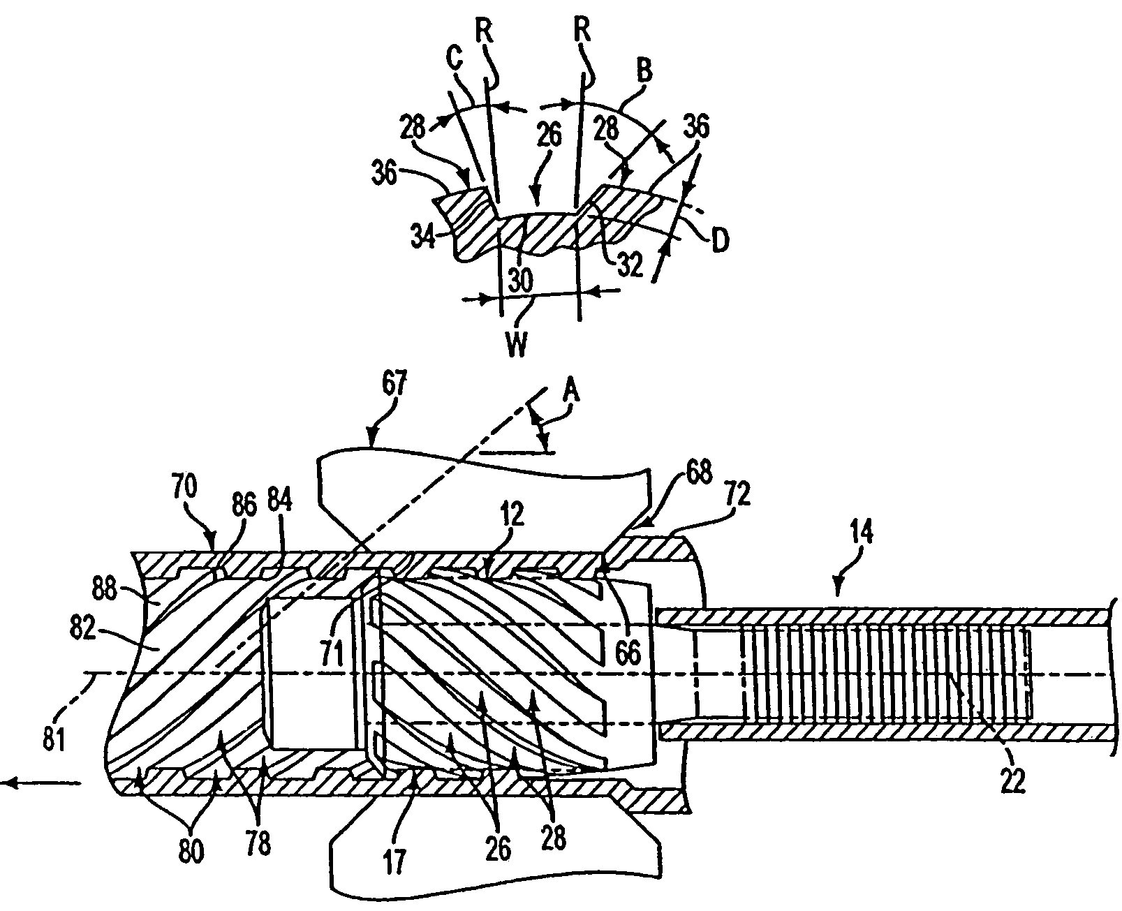
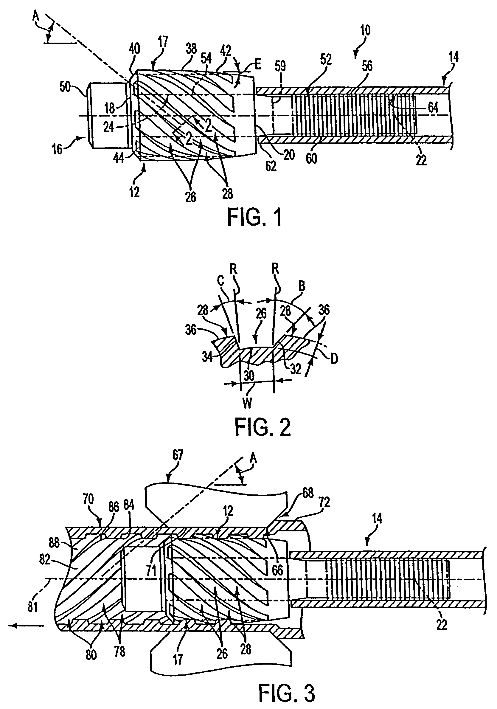
[0030]A plug tool 10 according to the present invention is depicted in FIG. 1 and comprises a drawing plug 12 assembled to a shaft 14 via a connector 16. The plug 12 has a plug body 17 with a forward end 18, a rearward end 20, a central longitudinal axis 22 and a bore 24 extending therethrough coaxial with the central longitudinal axis 22. The plug 12 is formed with a plurality of external grooves 26 extending longitudinally along the plug at a helix angle A to the central longitudinal axis 22. The grooves 26 are disposed at equally spaced locations about the central longitudinal axis 22 in alternating arrangement with external lands 28, with each groove 26 being disposed between a pair of adjacent lands 28. As seen in FIG. 1, each groove 26 terminates at a forward groove end and at a rearward groove end on the plug body 17. Each land 28 terminates at a forward land end and at a rearward land end on the plug body 17. As shown in cross-section normal to a groove 26 in FIG. 2, each gr...


PUM

PropertyMeasurementUnit
radial angleaaaaaaaaaa

Abstract

A plug tool for forming internally helically ribbed tube comprises a plug body for being rotatably disposed in a die orifice of a drawing die. The plug body has a central longitudinal axis, a plurality of external grooves equally spaced about the axis and a plurality of external lands in alternating arrangement with the grooves. The grooves extend along the plug body at a helix angle to the axis. Each groove has a normal cross-section defined by a root surface and opposing flank surfaces extending angularly outwardly from the root surface to adjacent land surfaces. The flank surfaces extend angularly outwardly from the root surface in opposite directions at different angles from one another. A method for forming internally helically ribbed tube involves drawing a length of tubing over the plug body rotatably disposed in a die orifice of a drawing die and constricting the tubing in the drawing die to force the tubing into the grooves of the plug body to form a plurality of internal helical ribs in the tubing in correspondence to the grooves.

Description

BACKGROUND OF THE INVENTION[0001]1. Field of the Invention[0002]The present invention relates generally to the formation of internally ribbed or rifled tubes and, more particularly, to plug tools for forming internal helical or spiral ribs in tubing, and to methods of producing internally helically or spirally ribbed or rifled tubes.[0003]2. Brief Discussion of the Related Art[0004]Internally ribbed or rifled tubes are used for various heat transfer or heat exchange applications including steam generating and superheating equipment such as boilers. Internally ribbed or rifled tubes present various advantages over plain bore tubes including the ability to sustain high heat transfer rates at higher pressures, higher enthalpies and lower mass fluxes than plain bore tubes.[0005]The advantage of using internally ribbed or rifled tubes in furnaces of boilers was recognized during the development of steam boilers. Initially, however, internally ribbed tubes were lap-welded tubes. Eventuall...

Claims


Application Information

Patent Timeline
Patent Type & Authority Patents(United States)
IPC IPC(8): B21C1/24B21C3/16B21C37/20
CPCB21C1/24B21C37/207B21C3/16
Inventor JESSON, JOHN E.SMITH, MICHAEL J.
Owner DOOSAN BABCOCK ENERGY AMERICA
Why Eureka
Try Eureka