
Microwave filter comprising a coaxial structure with a metallized foam having a periodic profile

a technology of periodic profile and microwave filter, which is applied in the direction of waveguides, waveguide types, basic electric elements, etc., can solve the problems of dielectric loss, complex and costly realization of such a coaxial structure microwave filter, etc., and achieve low cost production and high volume

Inactive Publication Date: 2008-04-08
THOMSON LICENSING SA
View PDF10 Cites 4 Cited by
  • Summary
  • Abstract
  • Description
  • Claims
  • Application Information

AI Technical Summary

Benefits of technology

[0004]The invention proposes a coaxial structure microwave filter of a simpler and less expensive construction suitable for low cost volume production.
[0005]For this purpose, the invention relates to a coaxial structure microwave filter constituted by a tube of synthetic foam material, the tube presenting a constant internal diameter and a fully metallized external surface with, in the axial direction, a profile according to a periodic or constant function and by a bar of a fully metallized synthetic material, with a constant external profile or following a periodic function, the largest diameter of the bar being noticeably equal to the internal diameter of the tube so that the bar can be inserted into the tube while maintaining the tube and the bar coaxial. The foam used is preferably a polymethacrylimide foam known for its electrical characteristics approaching those of air, for its mechanical characteristics of rigidity and lightness and for its low cost price. In particular, a polymethacrylimide foam under the name of polymethacrylimide HF (high frequency) can be used.
[0009]With this construction, a microwave filter can easily be combined with a monopole type or dipole type antenna.
[0010]The invention extends to a method of producing a microwave filter as defined above according to which the periodic function is realized by thermoforming the foam tube or foam bar. In particular, as a thermoforming technique, hot press molding will preferably be used, which is adapted to an objective of high volume, low cost production.

Problems solved by technology

However, the realization of such a coaxial structure microwave filter proves to be complex and costly, particularly for maintaining the inner core and the outer core of the filter perfectly coaxial.
Spacers made from plastic or another dielectric material are generally used to maintain them coaxial but this introduces dielectric losses.

Method used


Image

  • Microwave filter comprising a coaxial structure with a metallized foam having a periodic profile
  • Microwave filter comprising a coaxial structure with a metallized foam having a periodic profile

Examples


Embodiment Construction

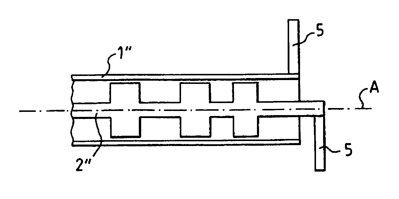
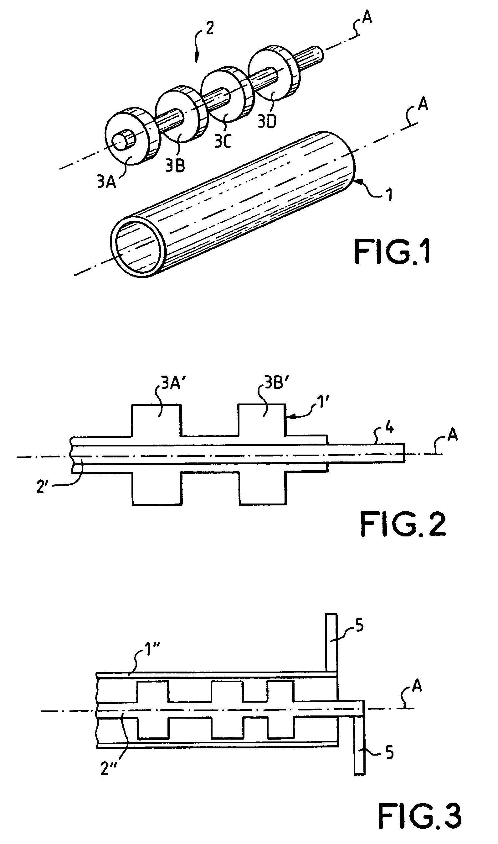
[0016]A first example of a coaxial structure microwave filter according to the invention is shown in FIG. 1 according to an exploded perspective view.

[0017]The outer conductive tube 1 and the inner conductive bar 2 of the filter are shown in FIG. 1 dissociated from each other for greater clarity, but it must be understood that the inner bar 2 extends according to the axial direction A inside the outer tube 1.

[0018]The inner bar 2 of the filter is constituted by a cylindrical bar made of synthetic foam whose outer surface follows a periodic function according to the axial direction. It preferably forms a succession of concentric crenelations 3A, 3B, 3C and 3D realizing the transfer function of the filter, for example a transfer function of a low-pass filter by defining successive sections of low characteristic impedance coaxial lines and high characteristic impedance coaxial lines. The shape of the foam bar 2 is realized by thermoforming, in particular according to a hot press moldin...


PUM


Abstract

The invention relates to a microwave filter comprising a coaxial structure, consisting of a tubular outer conductor and an inner bar conductor. According to the invention, the inner bar conductor extends in an axial direction inside the outer tube and, together with said tube, forms a series of concentric slots in the axial direction thereby defining successive coaxial line segments with low characteristic impedance and coaxial line segments with high characteristic impedance. The aforementioned concentric slots are produced in a synthetic foam block.

Description

[0001]This application claims the benefit, under 35 U.S.C. § 365 of International Application PCT / FR03 / 50200, filed Dec. 22, 2003, which was published in accordance with PCT Article 21(2) on Aug. 5, 2004 in French and which claims the benefit of French patent application No. 0300048, filed Jan. 3, 2003.[0002]The invention relates to a coaxial structure microwave filter comprising an outer conductive core and an inner conductive core extending according to an axial direction within the outer core and forming with this core a succession of concentric crenelations according to an axial direction defining successive sections of low characteristic impedance coaxial lines and high characteristic impedance coaxial lines.BACKGROUND OF THE INVENTION[0003]The work “Microwave Filters, Impedance-Matching Networks and Coupling Structures”, McGraw-Hill, 1962, describes such a microwave filter, in particular a low-pass filter, in which the outer conductive core is normally constituted by a cylindr...

Claims


Application Information

Patent Timeline
Patent Type & Authority Patents(United States)
IPC IPC(8): H01P1/202
CPCH01P1/202
Inventor LO HINE TONG, DOMINIQUELOUZIR, ALICHAMBELIN, PHILIPPEPERSON, CHRISTIANCOUPEZ, JEAN-PHILIPPE
Owner THOMSON LICENSING SA
Learn More