
Generator output line, in particular for a connection region in the generator base

a technology of output line and generator base, which is applied in the direction of insulated conductors, power cables, cables, etc., can solve the problems of increasing material costs, increasing the temperature of inner conductors and cladding tubes, etc., and achieves the effects of reducing material costs, reducing weight of aluminum, and being easy to work with than copper

Active Publication Date: 2006-03-28
SIEMENS ENERGY GLOBAL GMBH & CO KG
View PDF9 Cites 1 Cited by
  • Summary
  • Abstract
  • Description
  • Claims
  • Application Information

AI Technical Summary

Benefits of technology

[0010]There was therefore the need, in particular for connection regions in the generator base, to develop simpler and less expensive constructions for generator output lines.
[0011]An embodiment of the invention is therefore based on an object of providing a generator output line having a space-saving and, at the same time, simple construction which meets the electrical requirements and keeps to the thermal limit values. In particular, it is also suitable for use in connection regions in the generator base in the case of comparatively large rated unit powers of, for example, more than 18 kA.
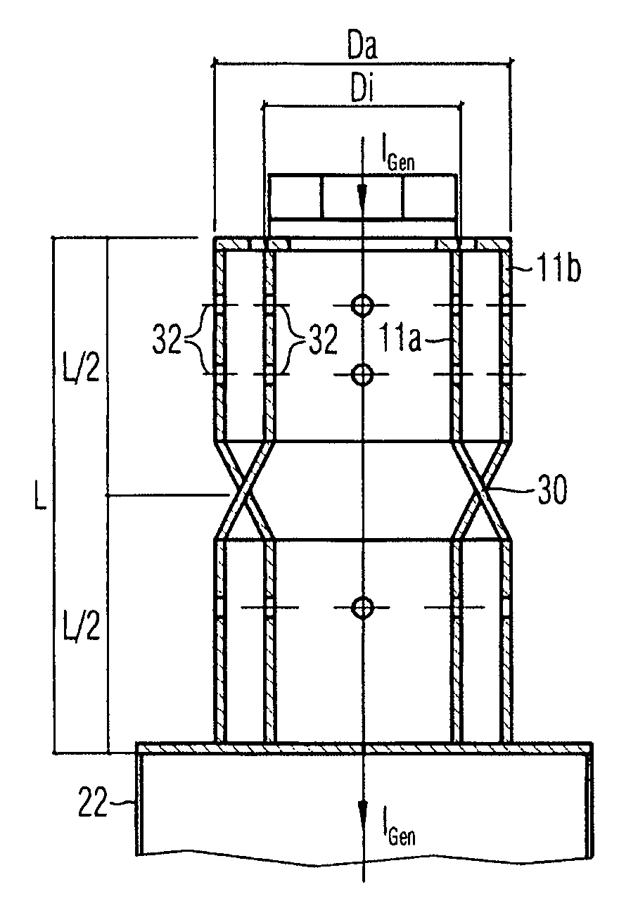
[0016]An aim is therefore to provide approximately the same flow of current in the two tubes of the inner conductor in the twin-tube solution for the inner conductor. This is achieved according to an embodiment of the invention by the current paths in the direct-axis direction of the inner conductor being changed at least once between the external tube and the internal tube of the inner conductor. By changing the current paths from the internal tube to the external tube and vice versa, the AC impedance, the electrical variable influencing the current distribution, between the two current paths and thus also the flow of current between the two current paths, can be made the same. By dividing the generator current between the internal tube and the external tube, it is possible to keep to the permissible temperature limit values, even if aluminum is used instead of copper for the inner conductor.
[0021]Avantages achieved by at least one embodiment of the invention include, in particular, that, for a space-saving and compact construction of a generator output line, aluminum can be used for the inner conductor. The use of aluminum is advantageous in terms of costs since the material costs are lower and it is easier to work with than copper. In addition, no complex soldering or welding connections are required between the copper and aluminum material. The lower weight of aluminum is also advantageous as regards transportation and handling on site.

Problems solved by technology

These currents result in I2R losses which lead to an increase in the temperature of the inner conductor and of the cladding tube.
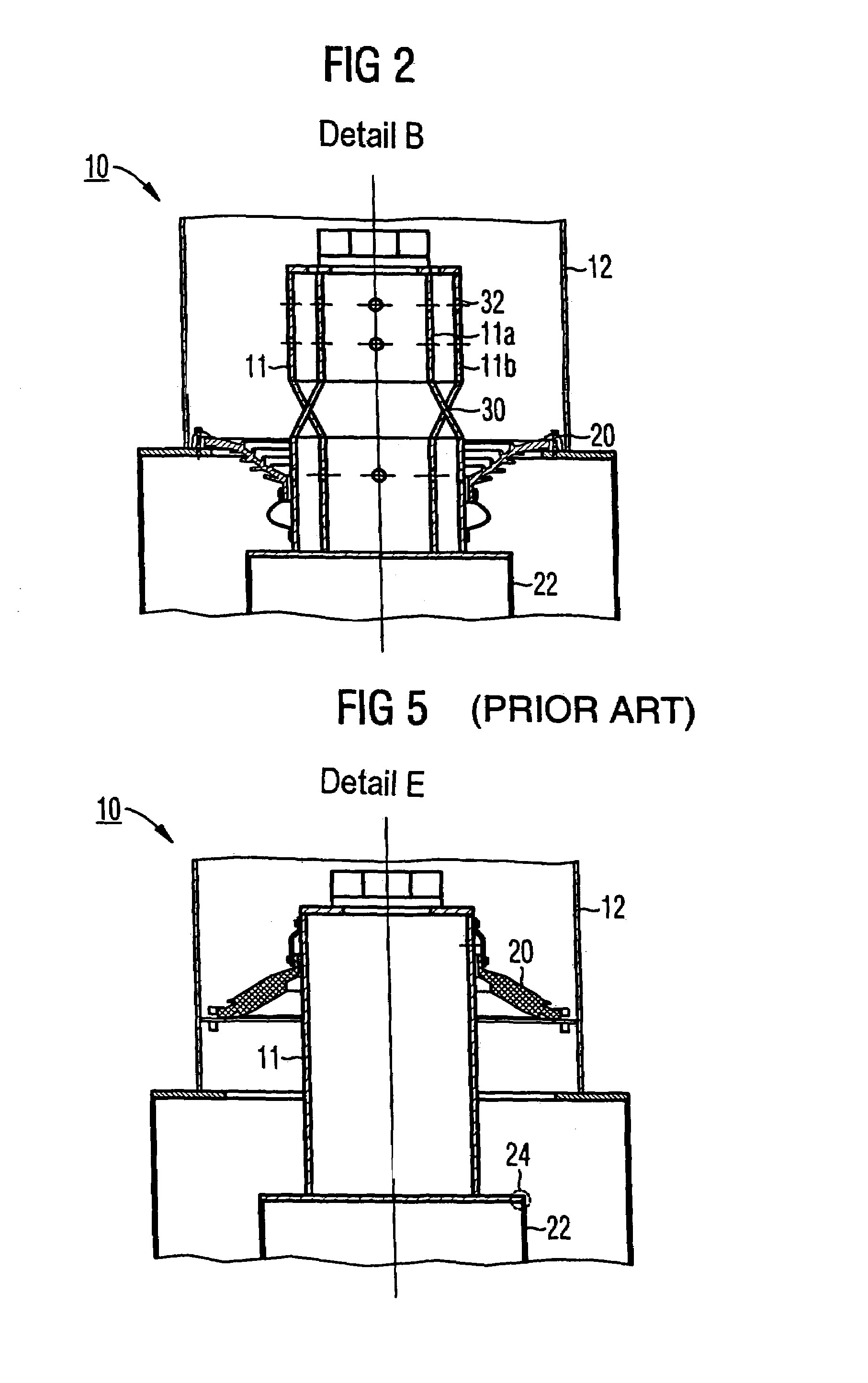
In addition to the increased material costs, the increased problems presented when welding and the increased weight of copper in comparison with aluminum, a particular problem with copper is the fact that it is necessary to provide a special soldered or welded electrical connection 24 between the thinner copper inner conductor 11 and the aluminum conductor tube 22 connected to it, which has a larger diameter.

Method used


Image

  • Generator output line, in particular for a connection region in the generator base
  • Generator output line, in particular for a connection region in the generator base
  • Generator output line, in particular for a connection region in the generator base

Examples


Embodiment Construction

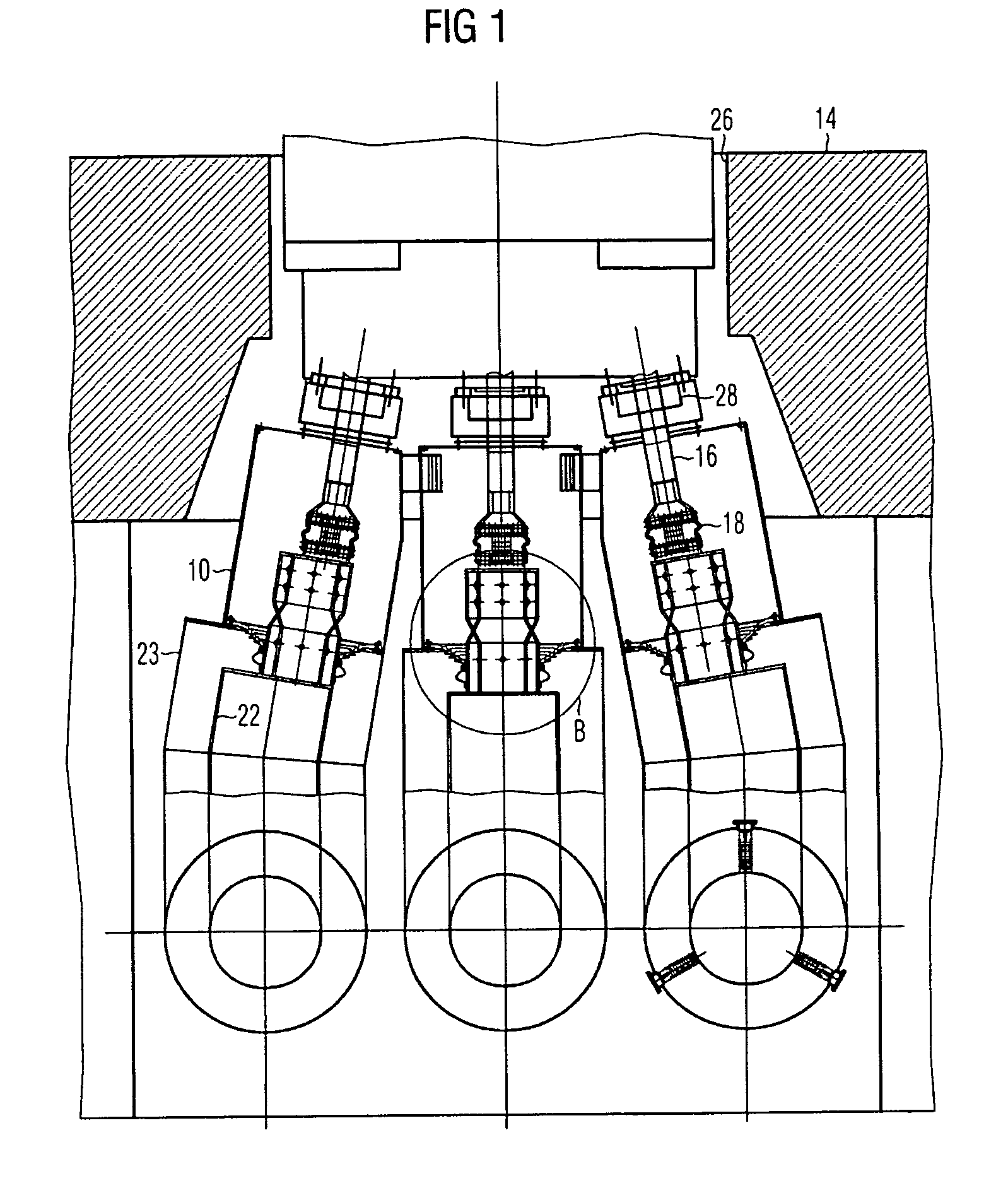
[0028]Described below is a preferred exemplary embodiment of a generator output line according to the present invention which can be advantageously used in a connection region in the generator base. For improved clarity, the same reference numerals are used for the same components or elements as in the conventional generator output line from FIGS. 4 and 5.

[0029]Provided in the generator base 14 of a generator is a generator base opening 26, through which the three electrical connections of the three-phase system are led out of the generator housing via connection pieces 28 and generator bushings 16. The generator output lines 10 of the three phases each include a cylindrical inner conductor 11 and a cladding tube connection region 12, which is arranged concentrically with respect to the inner conductor 11, for encapsulating the phases of the inner conductor 11. The inner conductors 11 are connected to the generator bushings 16 via flexible expanding copper strips 18 in order to ensu...


PUM

PropertyMeasurementUnit
electrical voltageaaaaaaaaaa
current intensityaaaaaaaaaa

Abstract

A generator output line is for electrically connecting a generator to a transformer. It includes a cylindrical inner conductor and a cylindrical cladding tube connection region which is arranged concentrically with respect to the inner conductor. The inner conductor is made up of an internal conductor tube and an external conductor tube, preferably in each case made of aluminum, and is constructed such that the current paths in the longitudinal direction of the inner conductor change at least once between the external conductor tube and the internal conductor tube.

Description

[0001]The present application hereby claims priority under 35 U.S.C. §119 on European patent application number EP 02023222.9 filed Oct. 16, 2002, the entire contents of which are hereby incorporated herein by reference.FIELD OF THE INVENTION[0002]The present invention genrally relates to a generator output line for electrically connecting a generator to a transformer. In particular, it relates to a generator output line of this type which can be used in a connection region in the generator base.BACKGROUND OF THE INVENTION[0003]Heavy-current connections, so-called generator output lines, are the electrical connection between a stator winding of a generator within a generator housing and an associated generator transformer or unit-connected transformer in power plants. This electrical connection usually has a phase-isolated construction, i.e. each of the three current conductors of the three-phase system is arranged in a separate, likewise electrically conductive casing, a so-called ...

Claims


Application Information

Patent Timeline
Patent Type & Authority Patents(United States)
IPC IPC(8): H01R4/00H01F27/04H02K5/22
CPCH02K5/225H01F27/04
Inventor FEUERSTEIN, WINFRIEDSCHREINER, FRANZ
Owner SIEMENS ENERGY GLOBAL GMBH & CO KG
Learn More