Material transfer vehicle for use in asphalt paving

a technology for asphalt paving and material transfer, which is applied in the direction of roads, roads, construction, etc., can solve the problems of dumping an excessive amount of material, affecting the operation, and being difficult for truck drivers to remove an empty delivery truck, so as to reduce the weight, improve maneuverability, and reduce the complexity

Active Publication Date: 2007-01-09
ROADTEC
View PDF12 Cites 30 Cited by
  • Summary
  • Abstract
  • Description
  • Claims
  • Application Information

AI Technical Summary

Benefits of technology

[0008]Among the advantages of the invention is that it provides a material transfer vehicle which does not require three conveyors as does the prior art vehicle. Consequently, the improved vehicle of the invention is somewhat less complex and may have a significantly reduced weight. An advantage of a preferred embodiment of the invention is that it provides a four-wheeled material transfer vehicle in which both front and rear wheels are steerable for improved maneuverability. Another advantage of a preferred embodiment of the invention is that it provides such a vehicle with improved asphalt remixing capability in the surge bin.
[0009]Other advantages and features of this invention will become apparent from an examination of the drawings and the ensuing description.
[0010]As used herein, the term “aggregate materials” refers to crushed stone and other particulate materials that are used in the production of asphalt, such as, for example, crushed limestone and other types of crushed stone, crushed or comminuted recycled asphalt paving materials, crushed, shredded or comminuted shin

Problems solved by technology

Sometimes, problems may arise when operating the paving machine and the delivery trucks in this manner.
Because of traffic conditions and other unforeseen delays, it is not uncommon for the paving machine to empty its hopper of asphalt before a loaded delivery truck is available to begin dumping its asphalt into the hopper.
Sometimes, it is simply impossible for the truck drivers to remove an empty delivery truck from engagement with the front of the paving machine and to maneuver a loaded truck into position to dump into the hopper before the hopper is emptied.
Then, when the paving machine resumes its forward motion, the screed will tend to ride upwardly momentarily, thus depositing an excessive amount of material.
Consequently, stopping of the paving machine causes a depression and a bump in the surface of the asphalt mat, resulting in an uneven pavement surface.

Method used


Image

  • Material transfer vehicle for use in asphalt paving
  • Material transfer vehicle for use in asphalt paving
  • Material transfer vehicle for use in asphalt paving

Examples


first embodiment

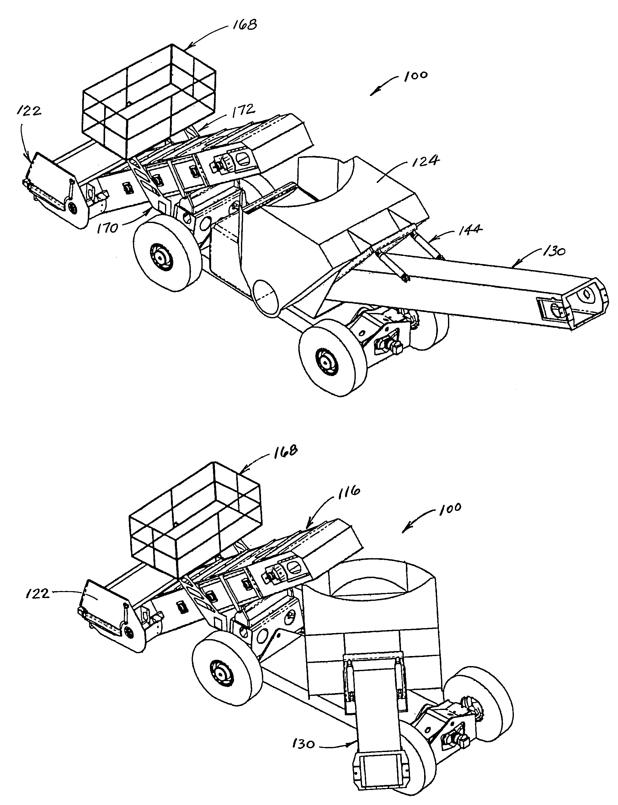
[0052]the invention is illustrated in FIGS. 4–18 and 20–22. As shown in FIGS. 4–17, self-propelled material transport vehicle 100 includes frame 102 having a front end at 104 and a rear end at 106. Vehicle 100 includes a vehicle drive system which is operatively attached to frame 102 and adapted to drive the vehicle along a roadway surface. As shown in FIGS. 4–17, the vehicle drive system includes a front wheel set comprised of left front wheel 108 and right front wheel 109 and a rear wheel set comprised of left rear wheel 110 and right rear wheel 111. Preferably, as illustrated in the drawings, each wheel set is comprised of a pair of wheels with pneumatic tires; however, other wheel sets such as are known to those having ordinary skill in the art to which the invention relates may alternatively be used. Each wheel of a wheel set is connected to an axle that is driven by a hydraulic motor (not shown) which is supplied with fluid under pressure by one or more hydraulic pumps (also n...

second embodiment

[0063]FIGS. 23–26 illustrate the invention. As shown therein, self-propelled material transport vehicle 200 includes frame 202 having a front end at 204 and a rear end at 206. Vehicle 200 includes a vehicle drive system which is operatively attached to frame 202 and is adapted to drive the vehicle along a roadway surface. This vehicle drive system includes a front wheel set comprised of left front wheel 208 and right front wheel 209 and a rear wheel set comprised of left rear wheel 210 and right rear wheel 211. Each wheel of a wheel set is connected to an axle that is driven by a hydraulic motor (not shown) which is supplied with fluid under pressure by one or more hydraulic pumps (also not shown). This hydrostatic drive system is similar to the hydrostatic drive systems of vehicles 10, 40 and 100. An engine (located in compartment 212) provides the motive force for the hydraulic pumps. In this embodiment of the invention, it is preferred that the same steering modes be provided as ...


PUM


Abstract

A material transfer vehicle for transporting asphalt from a delivery truck to a paving machine includes a frame and a vehicle drive system. The vehicle also includes a turret that is rotatably mounted on the frame and a surge bin that is mounted on the turret. The surge bin has a front side and a rear side with a discharge opening therein. A truck-unloading conveyor is mounted on the frame. The truck-unloading conveyor has an inlet end, and an outlet end which is adjacent to the front side of the surge bin. A paver-loading conveyor is mounted on the turret and has an inlet end extending into the discharge opening on the rear side of the surge bin.

Description

CROSS REFERENCE TO RELATED APPLICATION[0001]This application claims the benefit of provisional Application No. 60 / 660,618, which was filed on Mar. 11, 2005.FIELD OF THE INVENTION[0002]The present invention relates generally to a self-propelled vehicle that is adapted for transferring asphalt from a supply truck to an asphalt paving machine.BACKGROUND OF THE INVENTION[0003]Paving of roadways with asphalt is generally carried out by an asphalt paving machine and a number of supply trucks which transport the asphalt from an asphalt production plant to the paving machine. The paving machine generally is self-propelled and driven by a wheeled or tracked drive system. A hopper is located at the front end of the machine to receive asphalt from a truck, and a floating screed is located at the rear end of the machine to form the asphalt mat. A conveyor system typically comprised of slat conveyors and screw augers delivers the asphalt from the hopper to the road base just ahead of the screed....

Claims


Application Information

Patent Timeline
IPC IPC(8): E01C19/18
CPCE01C19/48E01C2301/04
Inventor HOFFMANN, JOHN E.SWEARINGEN, DAVID
Owner ROADTEC
Why Eureka
Try Eureka