

Connecting structure for a striking plate of a golf club head
a golf club head and connecting structure technology, applied in the field of connecting structure for golf club head striking plate, can solve the problems of increasing overall time for manufacturing golf club head and manufacturing cost, insufficient remaining welding material, and prone to cracks in welding areas, so as to reduce manufacturing cost, simplify assembly and positioning, and improve bonding strength
- Summary
- Abstract
- Description
- Claims
- Application Information
AI Technical Summary
Benefits of technology
Problems solved by technology
Method used
Image

Examples
first embodiment
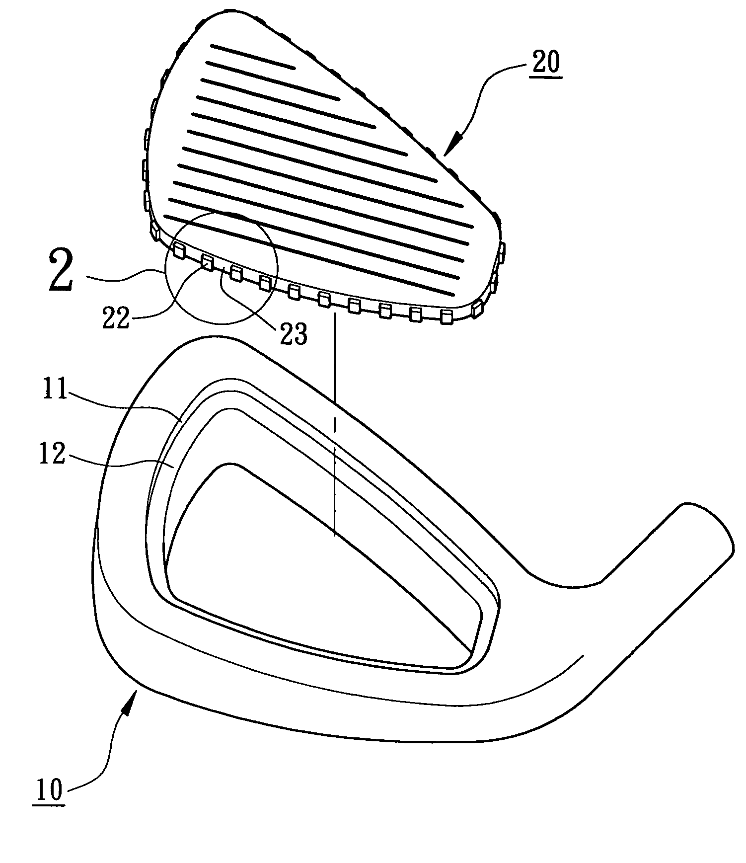
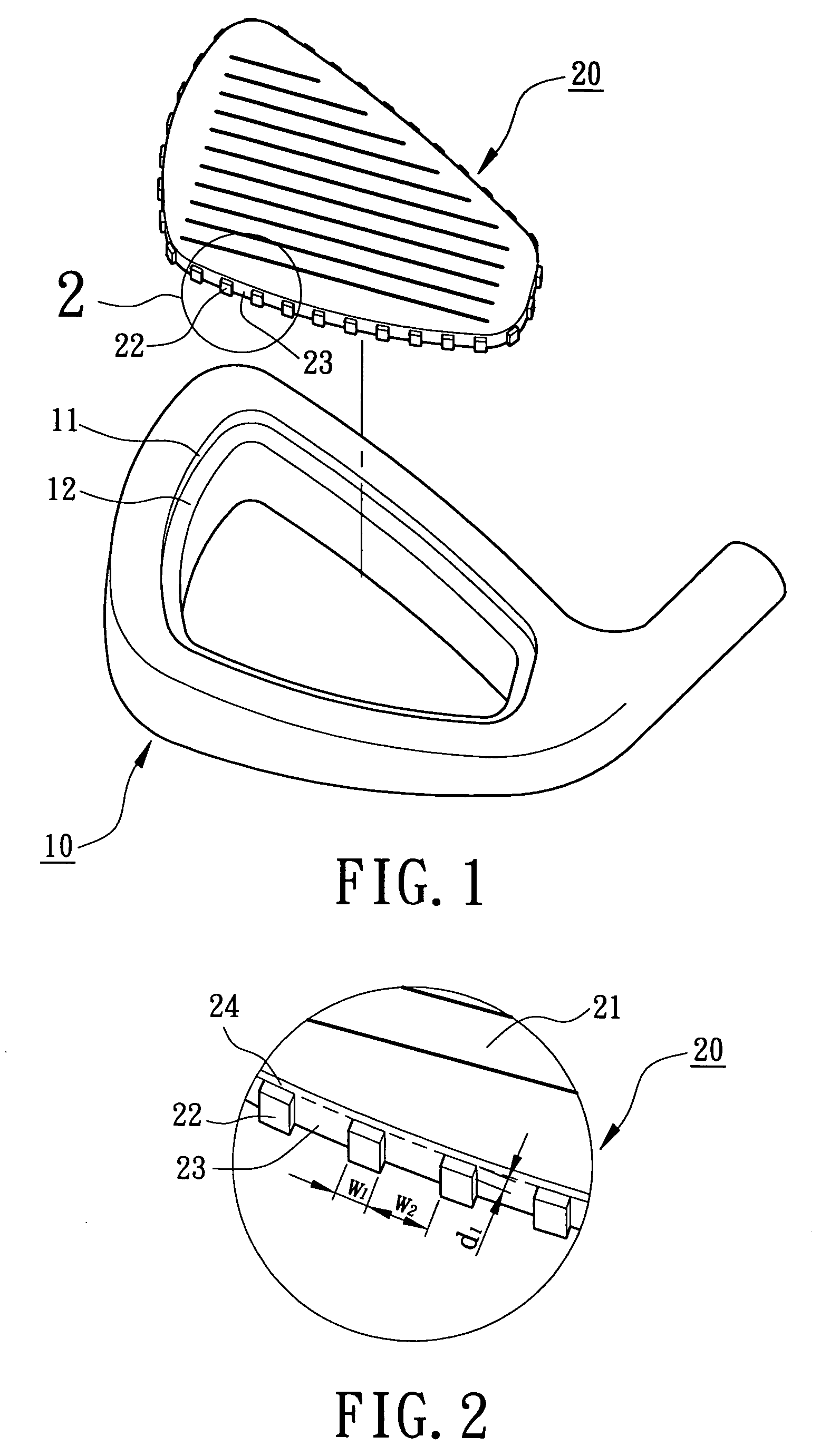
[0027]Referring to FIGS. 1 and 2, a golf club head in accordance with the present invention comprises a body 10 and a striking plate 20. The body 10 is made of stainless steel, carbon steel, or titanium alloy and has a recess 11. The recess 11 of the body 10 includes a stepped portion 12 extending inward from an inner perimeter delimiting the recess 11. The rear side of the recess 11 may be open or sealed.
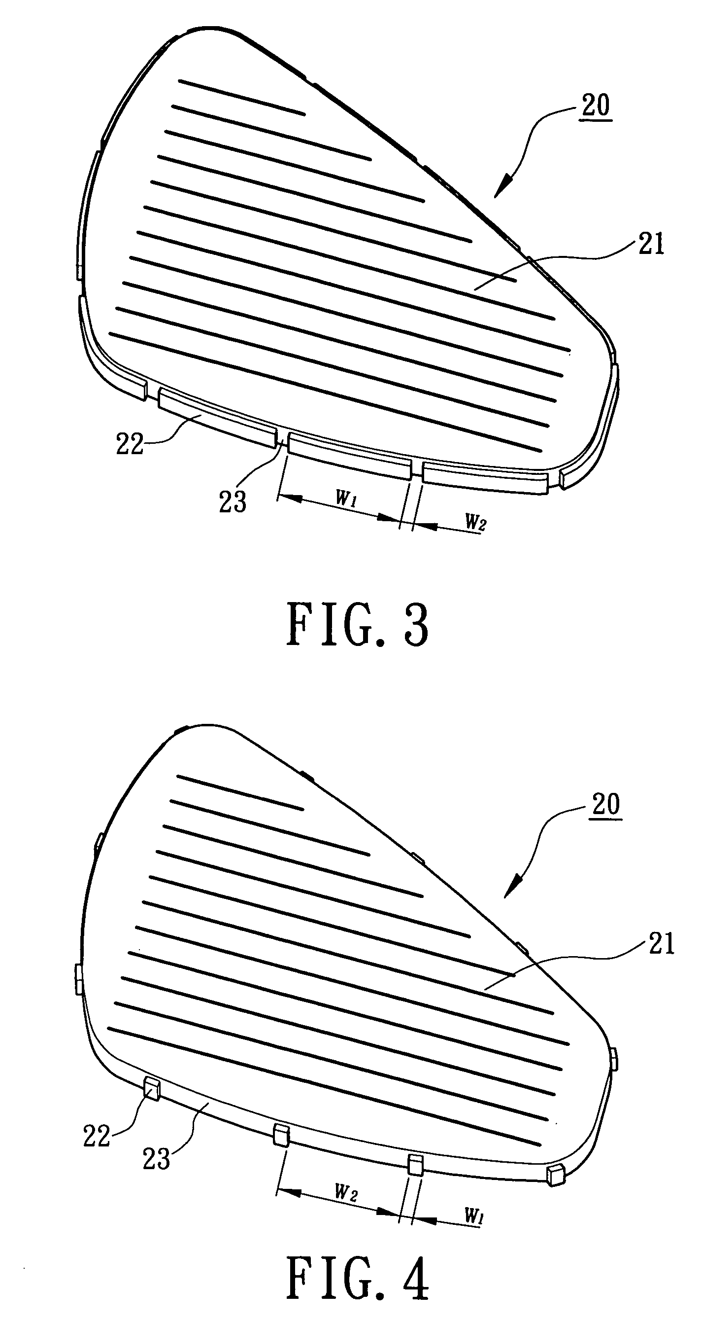
[0028]The striking plate 20 is made of titanium, titanium alloy, or stainless steel that has a good elastic deformability. The striking plate 20 includes a striking face 21 on a front side thereof for striking a golf ball. Further, a plurality of positioning protrusions 22 project from a perimeter of the striking plate 20, with a buffering space 23 being defined between two positioning protrusions 22 adjacent to each other. In this embodiment, each positioning protrusion 22 is a parallelepiped extending from a bottom edge of the perimeter of the striking plate 20 toward a top edge ...
second embodiment
[0035]Referring to FIGS. 12 and 13, the golf club head in accordance with the present invention comprises a body 10 and a striking plate 20. The body 10 includes a recess 11 having a stepped portion 12. In this embodiment, a plurality of positioning protrusions 13 project from an inner perimeter delimiting of the recess 11 of the body 10, with a buffering space 14 being defined between two positioning protrusions 13 adjacent to each other. Each positioning protrusion 13 may be a parallelepiped, trapezoid column, semi-cylinder, or a triangular prism illustrated in the above embodiments. In this embodiment, each positioning protrusion 13 is a parallelepiped extending from a bottom edge of the inner perimeter delimiting the recess 11 toward a top edge of the inner perimeter delimiting the recess 11. As illustrated in FIG. 13, preferably, a space 15 for receiving filler is defined between each positioning protrusion 13 and a top edge of the inner perimeter delimiting the recess 11.
[0036...
PUM
 Abstract
Description
Claims
Application Information