Cathodic protection system

a cathodic protection and cathodic technology, applied in the field of galvanic cathodic protection of steel, can solve the problems of substantial increase in the protective current delivered by the anode, and achieve the effect of improving the performance and service life of the embedded anode and enhancing the performance of the sacrificial anod

Inactive Publication Date: 2007-01-09
THE EUCLID CHEM CO
View PDF5 Cites 23 Cited by
  • Summary
  • Abstract
  • Description
  • Claims
  • Application Information

AI Technical Summary

Benefits of technology

[0014]The present invention relates to cathodic protection of reinforced concrete and, more particularly, to improving the performance and service life of embedded anodes prepared from sacrificial metals such as zinc, aluminum, and alloys thereof. The present invention more specifically relates to cathodic protection wherein the performance of the sacrificial anode is enhanced by the use of deliquescent or hygroscopic chemicals, known collectively as humectants. The humectants may be lithium nitrate, lithium bromide and mixtures of these two.
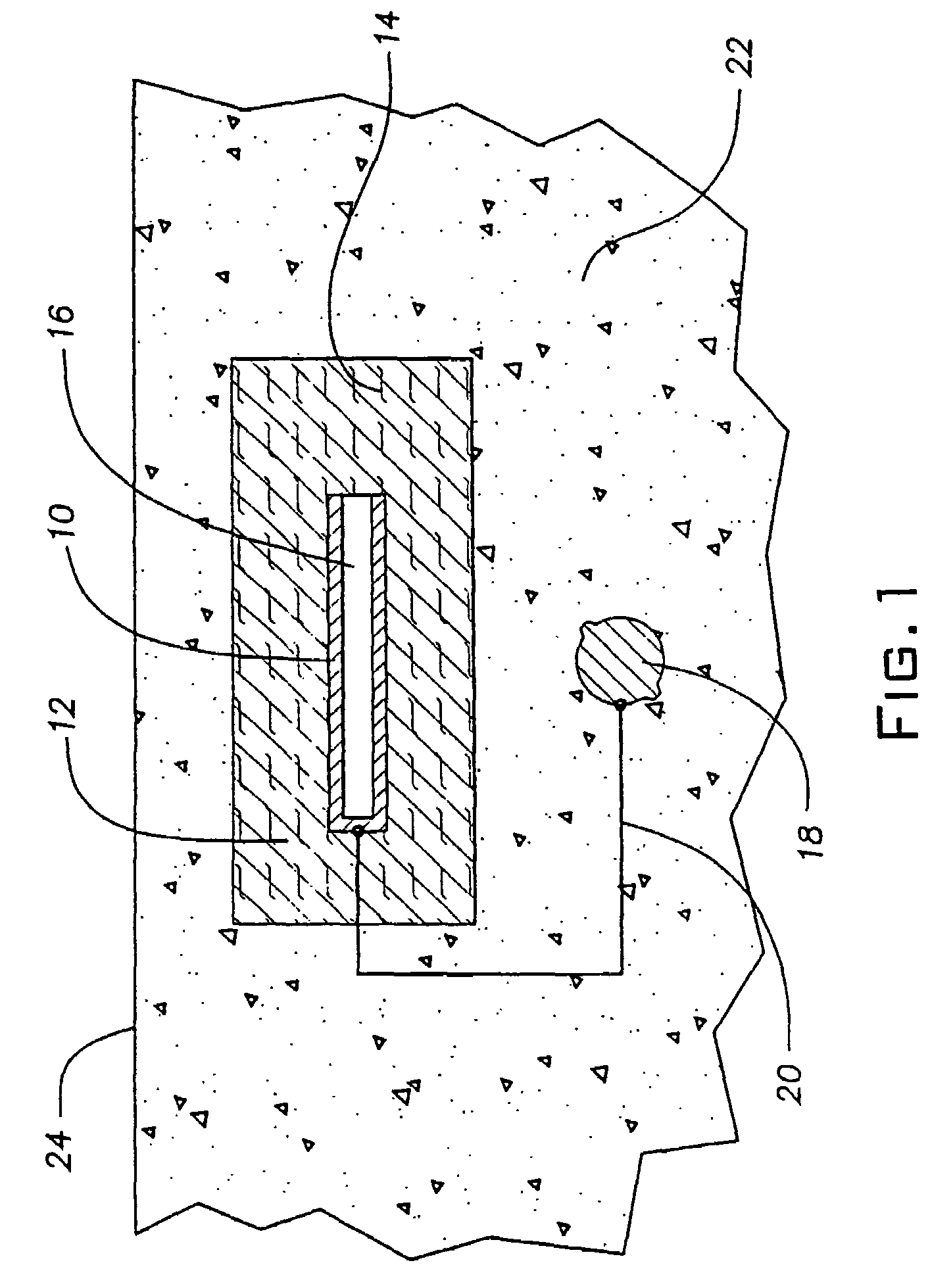
[0018]In another embodiment of the present invention, the matrix surrounding the anode contains a plurality of small voids constituting from 15% to 50% of the volume of the mortar matrix. It is preferred that the voids constitute from 20% to 35% of the volume of the mortar matrix. Such matrix is also capable of absorbing expansion of the anode due to compression without transmission of stress to the surrounding concrete.

Problems solved by technology

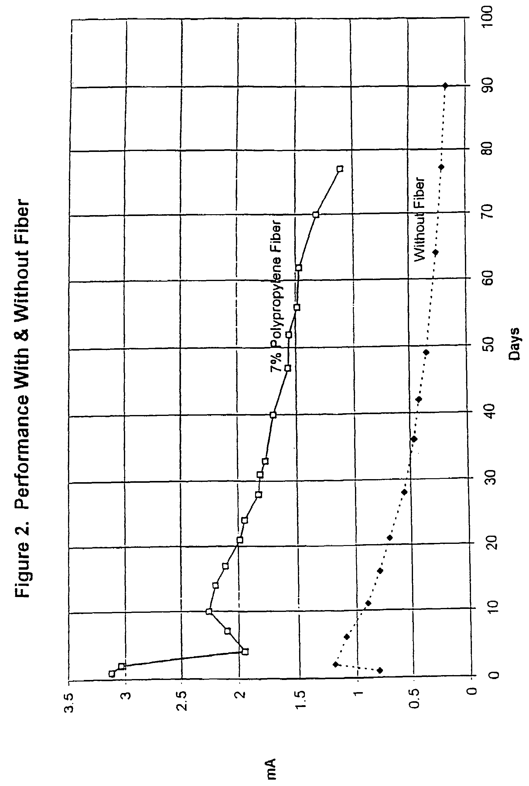
Surprisingly, it has also been found that mortars thus prepared with fibers of these types and amounts result in a substantial increase in protective current delivered by the anode.

Method used


Image

  • Cathodic protection system
  • Cathodic protection system

Examples


example 1

[0037]A sacrificial metal anode was constructed using pure zinc sheet expanded to the dimensions 1.25-inches (3.18-centimeters) LWD (long-way dimension) and 0.25-inch (0.64-centimeter) SWD (short way dimension). An anode was cut from this expanded zinc with the dimension 1.25-inch×0.75-inch (3.18 centimeter×1.91 centimeter), or one LWD×three SWD. This provided a zinc metal anode of relatively high surface area. An insulated #16 AWG copper wire was soldered to the zinc anode to provide an electrical connection, and the connection was coated with non-conductive epoxy. A 10-ohm resistor was soldered into the wire from the zinc anode to permit monitoring of the flow of current with time.

[0038]The zinc anode was cast in the center of a round “puck” of mortar designed to enhance the performance of the zinc anode. The mortar mix consisted of Eucopatch, a proprietary one-part, fast-setting, patch and repair material manufactured by The Euclid Chemical Company, and a mixture of 40% by volume...

example 2

[0043]A sacrificial metal anode was constructed using pure zinc sheet expanded to the dimensions 1.00-inches (2.54-centimeters) LWD (long-way dimension) and 0.312-inch (0.79-centimeter) SWD (short way dimension). An anode was cut from this expanded zinc with the dimension 1.00-inch×1.25-inch (2.54 centimeter×3.17 centimeter), or one LWD×four SWD. This provided a zinc metal anode of relatively high surface area approximately equal to the anode used in Example 1. An insulated #16 AWG copper wire was soldered to the zinc anode to provide an electrical connection, and the connection was coated with non-conductive epoxy. A 10-ohm resistor was soldered into the wire from the zinc anode to permit monitoring of the flow of current with time.

[0044]The zinc anode was cast in the center of a round “puck” of mortar designed to enhance the performance of the zinc anode. The mortar mix consisted of a proprietary mixture formulated by The Euclid Chemical Company containing two grades of fine aggre...


PUM

PropertyMeasurementUnit
lengthaaaaaaaaaa
thickaaaaaaaaaa
thickaaaaaaaaaa

Abstract

The cathodic protection system of a concrete structure (22) uses sacrificial anodes such as zinc, aluminum and alloys thereof embedded in mortar. A humectant is employed to impart high ionic conductivity to the mortar in which the anode is encapsulated. Lithium nitrate and lithium bromide and combinations thereof are preferred as the humectant. The anode (10) is surrounded by a compressive, conductive matrix (12) incorporating a void volume between 15% and 50% to accommodate the sacrificial corrosion products of the anode. A void space of at least 5% of the total volume of the anode (12) may be provided opposite to the active face of the anode. Synthetic fibers such as polypropylene, polyethylene, cellulose, nylon and fiberglass have been found to be useful for forming the matrix. A tie wire is used to electrically connect the anode to the reinforcing bar.

Description

BACKGROUND OF THE INVENTION[0001]1. Technical Field[0002]This invention generally relates to the field of galvanic cathodic protection of steel embedded in concrete structures, and is particularly concerned with the performance of embedded sacrificial anodes, such as zinc, aluminum, and alloys thereof.[0003]2. Background Art[0004]The problems associated with corrosion-induced deterioration of reinforced concrete structures are now well understood. Steel reinforcement has generally performed well over the years in concrete structures, such as bridges, buildings, parking structures, piers, and wharves, since the alkaline environment of concrete causes the surface of the steel to “passivate” such that it does not corrode. Unfortunately, since concrete is inherently somewhat porous, exposure to salt over a number of years results in the concrete becoming contaminated with chloride ions. Salt is commonly introduced in the form of seawater, set accelerators, or deicing salt.[0005]When the...

Claims


Application Information

Patent Timeline
Patent Type & Authority Patents(United States)
IPC IPC(8): C23F13/02
CPCC23F13/02C23F2201/02
Inventor BENNETT, JOHN E.
Owner THE EUCLID CHEM CO
Why Eureka
Try Eureka