
Detector constructed from electrically conducting fabric

a technology of electrical conductors and electrodes, which is applied in the direction of resistors, knitting, conductors, etc., can solve the problems of limiting the application area of electrodes, unable to identify two or more separate touches, and significant construction costs

Inactive Publication Date: 2007-01-09
WEARABLE TECH LTD
View PDF32 Cites 52 Cited by
  • Summary
  • Abstract
  • Description
  • Claims
  • Application Information

AI Technical Summary

Benefits of technology

[0012]An advantage of this configuration is that each of the conducting layers may be manufactured as a homogenous sheet using conventional textile manufacturing techniques. Furthermore, when assembled in the form of a detector, the detector itself remains flexible and all of the advantages of its textile construction may be utilised.

Problems solved by technology

A problem with this configuration is that it is only capable of detecting a single touch and cannot identify two or more separate touches.
A problem with this approach to providing a multiplexed sheet is that the construction of such a sheet is relatively difficult and thereby leads to significant constructional costs; thereby limiting its area of application.
In addition, this approach requires the use of a 5-wire system, as distinct from the preferred 4-wire system, resulting in non-uniform electric fields and a requirement for compensation to be provided.
This introduces further problems in terms of calibration and also in terms of loss of resolution.
Manual pressure applied at particular regions may be detected by the intersection of a particular row and column being brought into contact but the presence of a continuous metal layer significantly restricts the flexibility of the device as a whole.
This is emphasised by the fact that the device is to be constructed upon a rigid board and as such many of the benefits from using a fabric material are effectively lost.

Method used


Image

  • Detector constructed from electrically conducting fabric
  • Detector constructed from electrically conducting fabric
  • Detector constructed from electrically conducting fabric

Examples


Embodiment Construction

FIG. 1

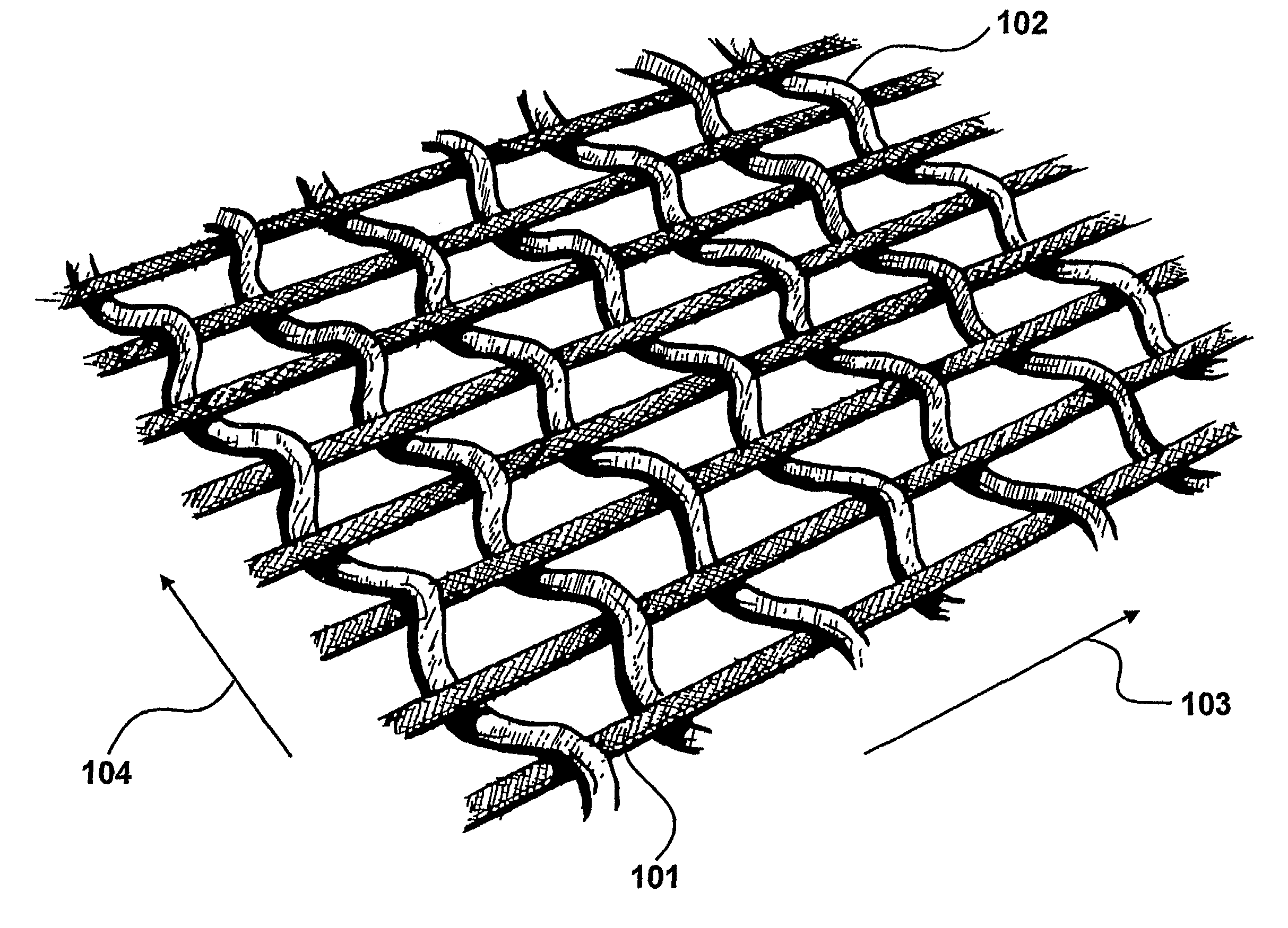
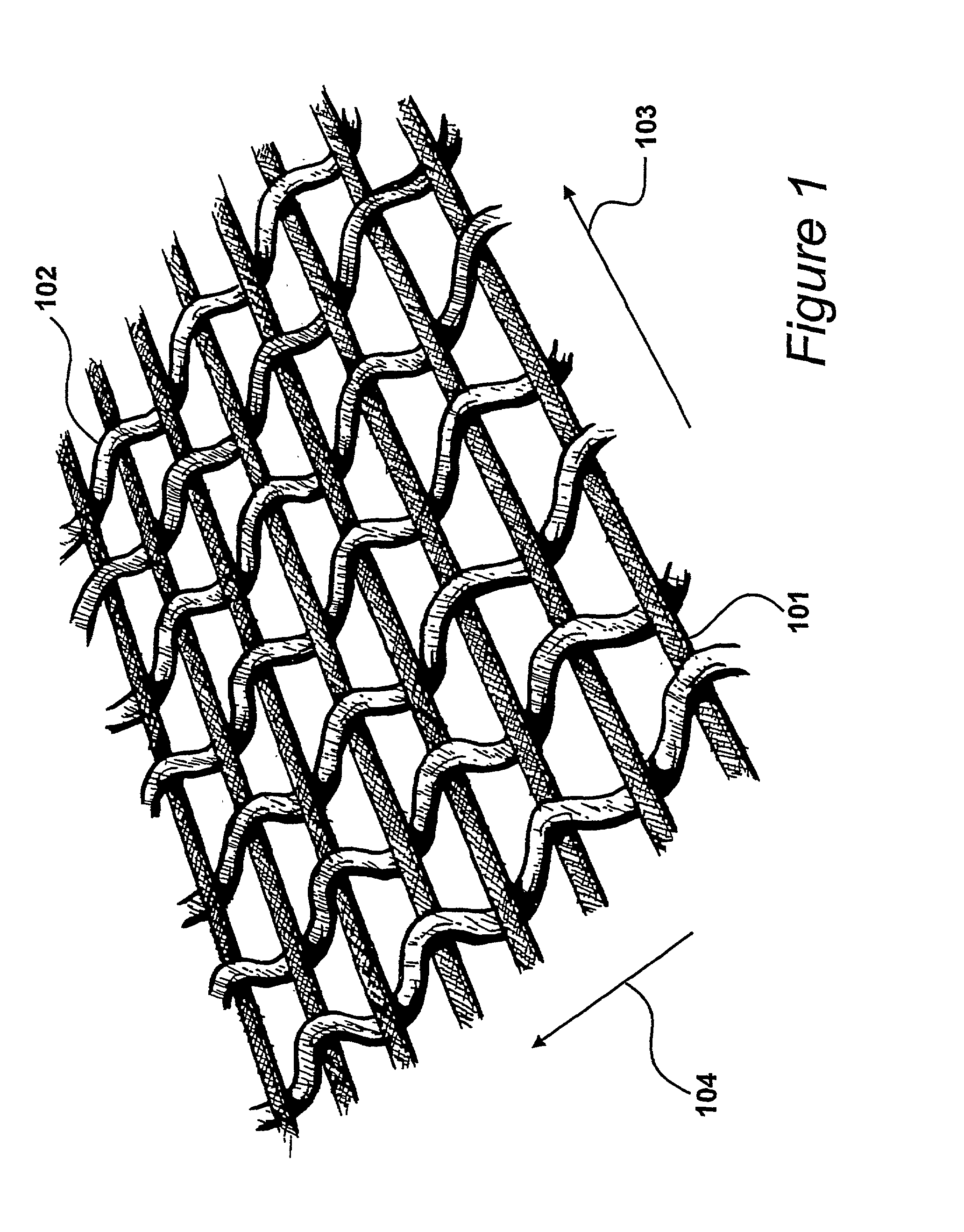
[0040]A woven fabric is shown in FIG. 1 of a type suitable for application in a detector made in accordance with the present invention. The woven fabric has a warp made from single filaments of carbon coated nylon-6, available from BASF under the trademark “RESISTAT” and identified by the designation F901. F901 is a fibre produced primarily for use in static dissipation applications in fabrics. Many different sizes of filament may be employed, dependant upon the requirements of an application, and in this example the size of the filaments is twenty-four decitex, (twenty-four grams per 10,000 m) presenting a diameter of fifty-two micrometers.

[0041]Weft fibres 102 are fabricated from a polyester yarn of similar dimensions to the warp. These polyester weft yarns are non-conductive such that the resulting fabric is conductive along the warp, in direction 103 but not conductive in the orthogonal weft direction, as illustrated by arrow 104. Thus, due to the nature of the weave of th...


PUM

PropertyMeasurementUnit
Lengthaaaaaaaaaa
Forceaaaaaaaaaa
Pressureaaaaaaaaaa

Abstract

The present invention relates to a detector constructed from electrically conducting fabric and configured to present a varying electrical characteristic in response to a mechanical interaction. The detector comprises a first conducting layer (401) which is displaced from a second conducting layer (402) such that conduction between the layers results when the layers are mechanically forced together. In addition, the first of the layers has a plurality of lengths of conductive yarn and a plurality of lengths of non-conductive yarn machined therein, such that at least one length of conductive yarn is electrically isolated from another of the lengths of conductive yarn and the conducting yarns in the first of the layers are electrically grouped to define a plurality of identifiable rows. Each identifiable row has a respective electrical conductor; and define specific regions of the detector.

Description

BACKGROUND OF THE INVENTION[0001]The present invention relates to a detector constructed from electrically conducting fabric and configured to present a varying electrical characteristic in response to a mechanical interaction.[0002]A fabric touch sensor for providing positional information is disclosed in U.S. Pat. No. 4,659,873 of Gibson. The sensor of Gibson is fabricated using two layers of fabric having conducting threads, where said conducting layers are separated by a resistive layer to prevent unintentional contact. The Gibson device is primarily an overlay for a visual display unit whereby the position of finger contacts may be identified in response to the display of representational icons, such as buttons etc. An electrical potential is applied across at least one of the layers and a voltage detected at a position of contact allows a position on the touch screen to be detected.[0003]A problem with this configuration is that it is only capable of detecting a single touch a...

Claims


Application Information

Patent Timeline
IPC IPC(8): H01B7/08G06F3/023H01H13/702H01H13/785
CPCG06F3/023H01H13/702H01H13/785H01H2201/036H01H2203/0085H01H2229/00H01H2209/016H01H2215/004H01H2215/008H01H2223/046H01H2223/052H01H2203/01D04B1/12D10B2403/02431
Inventor SANDBACH, DAVID L
Owner WEARABLE TECH LTD
Learn More