
Electro-conductive fibers with carbon nanotubes adhered thereto, electro-conductive yarn, fibers structural object, and production processes thereof

a technology of carbon nanotubes and electro-conductivity, which is applied in the direction of physical treatment, transportation and packaging, coatings, etc., can solve the problems of easy generation of static electricity (or electrostatic charges) by synthetic fiber products, damage to electronic devices, and spoilage of beauty, etc., to minimize the change (or increase) in mass, excellent electro-conductivity, and excellent electro-conductivity

Active Publication Date: 2011-06-23
CHAKYU DYEING +2
View PDF9 Cites 21 Cited by
  • Summary
  • Abstract
  • Description
  • Claims
  • Application Information

AI Technical Summary

Benefits of technology

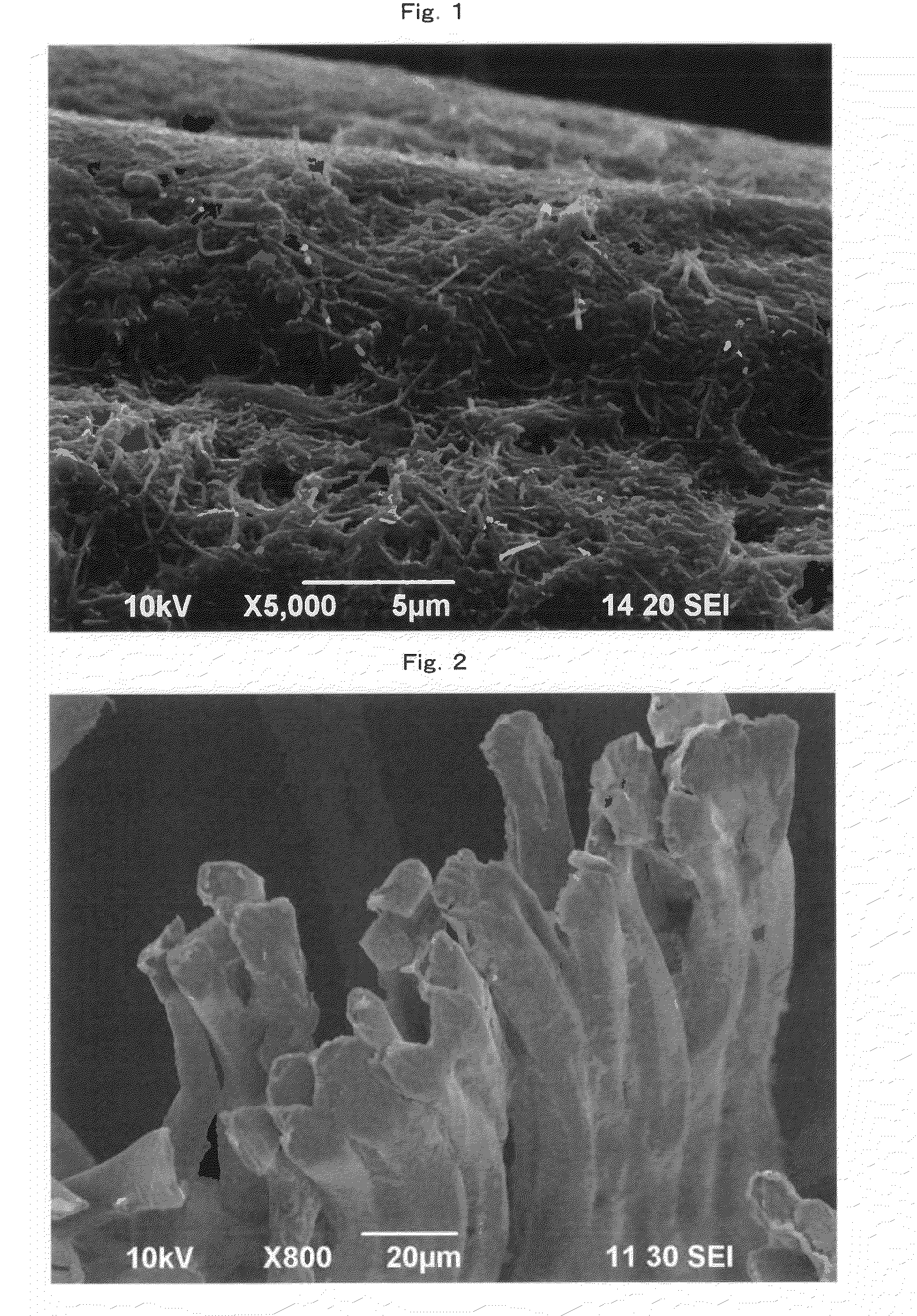
[0032]The electro-conductive fibers (including an electro-conductive yarn and synthetic fibers constituting an electro-conductive fibers structural object; the same applies hereinafter) of the present invention have carbon nanotubes homogeneously and firmly adhered to an almost whole of a fiber surface thereof. Therefore, the fibers have an excellent electro-conductivity. In addition, the adhesion of a small amount of the carbon nanotubes in extreme small size which have an excellent electro-conductivity, to the fiber surface minimizes the change (or increase) in mass caused by adhering the carbon nanotubes to the fibers and allows use of synthetic fibers having a small fiber diameter as the fibers, and therefore synthetic fibers having properties such as excellent softness, tactile sensing (or texture), workability, and easiness in handling in comparison with the conventional art are obtained. In particular, the electro-conductive fibers of the present invention have properties such as extremely excellent electro-conductive performance, electro-conductive heat generation performance, antistatic performance, electromagnetic wave and magnetic shielding performance, and heat conduction. Further, since the peeling off of the carbon nanotubes from the fiber surface due to washing, friction, or other reasons is hardly caused, the fibers have an excellent durability of each performance.
[0033]Furthermore, in a treatment with a dispersion, the carbon nanotubes can homogeneously be adhered to a synthetic fibers or a fibers structural object by vibrating (or microvibrating) the fibers of the fibers structural object (for example, at about 20 to 2000 Hz). In particular, when the fibers are a multifilament or a spun yarn (particularly, a multifilament), the dispersion permeates (or penetrates) the inside of a bundle of the multifilament or the spun yarn and the carbon nanotubes can be adhered over the inside of the fibers (particularly, a whole surface of every single filament of the multifilament) to give a uniform electro-conductive layer. The uniform electro-conductive layer ensures a stable electric resistance value in a threadline (or longitudinal) direction of the fibers. In addition to such a vibration treatment, use of a binder allows formation of a firmer electro-conductive layer.
[0034]Further, in the present invention, use of an aqueous dispersion obtained by dispersing carbon nanotubes in water in the presence of a surfactant (particularly, a zwitterionic surfactant) as a carbon nanotube dispersion ensures uniform adhesion of the carbon nanotubes to the fiber surface and provides fibers having a stable electric resistance value in a threadline direction thereof because the carbon nanotubes are well dispersed as a fine particle without cohesion (or aggregation) in the aqueous dispersion.
[0035]In particular, the electro-conductive fibers of the present invention, in which the carbon nanotubes form a uniform and thin-layered network structure and are firmly adhered to the fiber surface, are effectively available for various uses. These uses having the above-mentioned properties includes, for example, a clothing application (e.g., a working wear and a uniform) having an antistatic performance or an electromagnetic wave and magnetic shielding performance, an interior application (e.g., a curtain), a neutralizing bag filter, an electromagnetic wave shielding industrial material, a radiator, and a heating element sheet generating heat efficiently at a low voltage.

Problems solved by technology

However, a product with synthetic fibers easily generates static electricity (or electrostatic charges) by a cause such as friction.
The generation of the static electricity spoils the beauty of the product due to attachment of dust or gives a person an electrical shock or unpleasant tactile sensing by discharge.
In addition, the generation of static electricity sometimes causes a damage to an electronic apparatus due to spark on electrostatic discharge, or an ignition and explosion of an inflammable substance.
However, since electro-conductive particles (e.g., an electro-conductive carbons) directly-mixed into synthetic fibers scarcely and heterogeneously lie or appear on the surface of the fibers, the electro-conductive particles do not give electro-conductivity sufficiently, and a fabric made of those synthetic fibers is liable to vary in electro-conductivity.
Such a large fineness tends to result in disadvantages such as a decreased softness (or flexibility) of the synthetic fibers, a deteriorated workability (such as knitting and weaving), and a lowered tactile sensing (or flexible feel).
Further, the electro-conductive particle adhered to the fiber surface is easily peeled off due to friction, washing, or other reasons, and the durability of the electro-conductive performance deteriorates.
Furthermore, a product obtained by adhering an electro-conductive particle (e.g., a carbon black or a metal particle) to a fabric made of synthetic fibers by a means such as a binder has a low softness and easily causes peeling (or falling) off of the electro-conductive particle from the surface of the fabric.
In proportion to increase in the use, electromagnetic waves or magnetism have been scattered over life space, and there have been some problems, e.g., a disturbance of a human being due to electromagnetic waves or magnetism and an improper operation of an electronic apparatus.
However, the conventional electromagnetic wave shielding synthetic fiber or fabric in which an electro-conductive metal particle is contained or adhered has some problems such as performance deterioration and dust generation due to peeling (or falling) off of the adhered metal particle or piece, and is still unsatisfactory.
As a result, the present situation is that an intrinsic size merit of the carbon nanotubes due to a size thereof, the above-mentioned properties such as excellent mechanical property, electric conductivity, and thermal stability are still insufficiently utilized.
However, due to an ununiform covering of the carbon nanotubes on a surface of the fibers obtained by this method, the fibers have an insufficient electro-conductivity and low adhesion strength between the fibers and the carbon nanotubes, and the carbon nanotubes are easily peeled off from the fibers.
However, due to an ununiform covering of the fiber surface with the carbon nanotubes, the molded product has an insufficient electro-conductivity, and the mechanical property of the fibers is also deteriorated.

Method used


Image

  • Electro-conductive fibers with carbon nanotubes adhered thereto, electro-conductive yarn, fibers structural object, and production processes thereof
  • Electro-conductive fibers with carbon nanotubes adhered thereto, electro-conductive yarn, fibers structural object, and production processes thereof

Examples


example 1

[0135](1) Preparation of Aqueous Carbon Nanotube Dispersion:

[0136](i) An aqueous solution of the surfactant (pH 6.5) was prepared by mixing 2.0 g of 3-(dimethylstearylammonio)propanesulfonate (a zwitterionic surfactant), 5 ml of glycerin (a hydration stabilizer), and 495 ml of deionized water.

[0137](ii) In a ball mill body (cylinder type, internal volume=1800 ml, ball diameter=150 mm, and filling amount of ball=3200 g), 500 ml of the aqueous solution of the surfactant obtained in the above step (i) and 15.2 g of carbon nanotubes (“MWCNT-7” manufactured by Nano Carbon Technologies Co., Ltd.) were put, and the mixture was stirred by hand to give a paste product. Then the ball mill body was placed on a rotating stand (“AS ONE” manufactured by ASAHI RIKA SEISAKUSYO, Co., Ltd.), and the paste product was stirred for one hour to give a liquid product containing the carbon nanotubes.

[0138](iii) The whole quantity of the liquid product containing the carbon nanotubes produced in the above s...

example 2

[0146](1) Preparation of Aqueous Carbon Nanotube Dispersion:

[0147](i) An aqueous solution of the surfactant (pH 6.5) was prepared by mixing 2.0 g of 3-(dimethylstearylammonio) propanesulfonate (a zwitterionic surfactant), 5 ml of glycerin (a hydration stabilizer), and 495 ml of deionized water.

[0148](ii) In a ball mill body (cylinder type, internal volume=1800 ml, ball diameter=150 mm, and filling amount of ball=3200 g), 500 ml of the aqueous solution of the surfactant obtained in the above step (i) and 30.4 g of carbon nanotubes (Baytube, manufactured by Bayer) were put, and the mixture was stirred by hand to give a paste product. Then the ball mill body was placed on a rotating stand (“AS ONE” manufactured by Asahi Rika Kenkyusho, Co., Ltd.), and the paste product was stirred for one hour to give a liquid product containing the carbon nanotubes.

[0149](iii) The whole quantity of the liquid product containing the carbon nanotubes produced in the above step (ii) was removed from the ...

example 3

[0156](1) Preparation of Aqueous Carbon Nanotube Dispersion:

[0157](i) An aqueous solution of the surfactant (pH 6.5) was prepared by mixing 2.0 g of 3-(dimethylstearylammonio)propanesulfonate (a zwitterionic surfactant), 5 ml of glycerin (a hydration stabilizer), and 495 ml of deionized water.

[0158](ii) In a ball mill body (cylinder type, internal volume=1800 ml, ball diameter=150 mm, and filling amount of ball=3200 g), 500 ml of the aqueous solution of the surfactant obtained in the above step (i) and 10.2 g of carbon nanotubes (“MWCNT-7” manufactured by Nano Carbon Technologies Co., Ltd.) were put, and the mixture was stirred by hand to give a paste product. Then the ball mill body was placed on a rotating stand (“AS ONE” manufactured by Asahi Rika Kenkyusho, Co., Ltd.), and the paste product was stirred for one hour to give a liquid product containing the carbon nanotubes.

[0159](iii) The whole quantity of the liquid product containing the carbon nanotubes produced in the above st...


PUM

PropertyMeasurementUnit
Temperatureaaaaaaaaaa
Fractionaaaaaaaaaa

Abstract

Electro-conductive fibers comprise synthetic fibers and an electro-conductive layer containing carbon nanotubes and covering a surface of the synthetic fibers, and the coverage of the electro-conductive layer relative to the whole surface of the synthetic fibers is not less than 60% (particularly not less than 90%). The electric resistance value of the electro-conductive fibers ranges from 1×10⁻² to 1×10¹⁰ Ω / cm, and the standard deviation of the logarithm of the electric resistance value is less than 1.0. The thickness of the electro-conductive layer ranges from 0.1 to 5 μm, and the ratio of the carbon nanotubes may be 0.1 to 50 parts by mass relative to 100 parts by mass of the synthetic fibers. The electro-conductive layer may further contain a binder. The electro-conductive fibers may be produced by immersing the synthetic fibers in a dispersion with vibrating the synthetic fibers to form the electro-conductive layer adhered to the surface of the synthetic fibers. The electro-conductive fibers have the carbon nanotubes homogeneously and firmly adhered to an almost whole of a surface thereof and have an electro-conductivity and a softness.

Description

TECHNICAL FIELD[0001]The present invention relates to electro-conductive fibers with carbon nanotubes adhered thereto, an electro-conductive yarn containing the electro-conductive fibers, and a fibers structural object (fabric) containing the electro-conductive fibers, as well as production processes thereof. More specifically, the present invention relates to electro-conductive fibers, an electro-conductive yarn, and an electro-conductive fibers structural object, each having nano(nm)-sized fine carbon nanotubes homogeneously and firmly adhered to a fiber surface thereof, as well as production processes thereof.BACKGROUND ART[0002]Synthetic fibers such as polyester fibers, polyamide fibers, polyolefin fibers, or acrylic fibers have properties such as excellent mechanical properties, chemical resistance, weather resistance, and easiness in handling (or easy-to-handle), therefore the synthetic fiber is widely used for many purposes, including a clothing, a bedclothing, fiber products...

Claims


Application Information

Patent Timeline
IPC IPC(8): D02G3/36B05D5/12B82Y40/00
CPCD06M10/02D06M10/06Y10T428/292D06M2200/00D06M11/74
Inventor FUGETSU, BUNSHIAKIBA, EIJIHACHIYA, MASAAKI
Owner CHAKYU DYEING
Learn More