High performance radar display

a radar display and high-performance technology, applied in the field of display systems, can solve the problems of inability to transport the bitmap data from the scan converter to the graphics board at the required data rate without placing an excessive burden on the cpu

Active Publication Date: 2007-01-09
NORTHROP GRUMMAN SYST CORP
View PDF6 Cites 15 Cited by
  • Summary
  • Abstract
  • Description
  • Claims
  • Application Information

AI Technical Summary

Benefits of technology

[0011]In accordance with the present invention a scan conversion is provided which allows the scan converter to work with data in its most convenient format in a radar memory. A displayable image is mirrored to a graphics memory simultaneously with the write portion of the radar memory read-modify-write cycles of the scan conversion process. On every write to the radar memory, radar data is simultaneously converted to associated colors by indexing a color look-up table and writing the indexed color to the graphics memory over

Problems solved by technology

Present host computers are not capable of converting a 1024 by 1024 bitmap to a 32 bit true color at a fast enough rate for a radar display.
The scan conversion requires read-modify-write cycles to memory at a very high rate that is not practicable over a PCI bus due to the high latency times on the data reads.
The computer is not capable of transporting the bitmap data from the scan c

Method used


Image

  • High performance radar display
  • High performance radar display
  • High performance radar display

Examples


Embodiment Construction

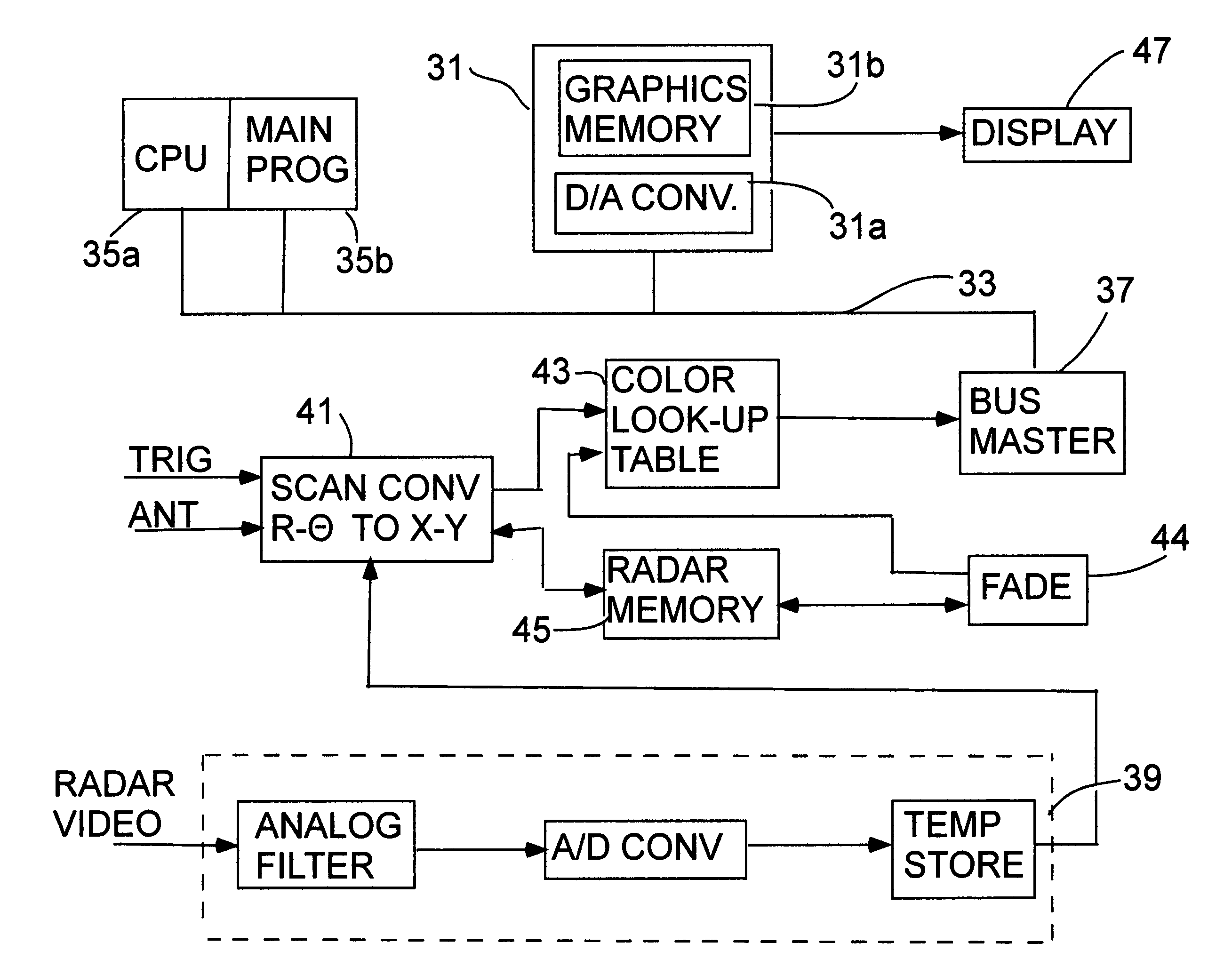
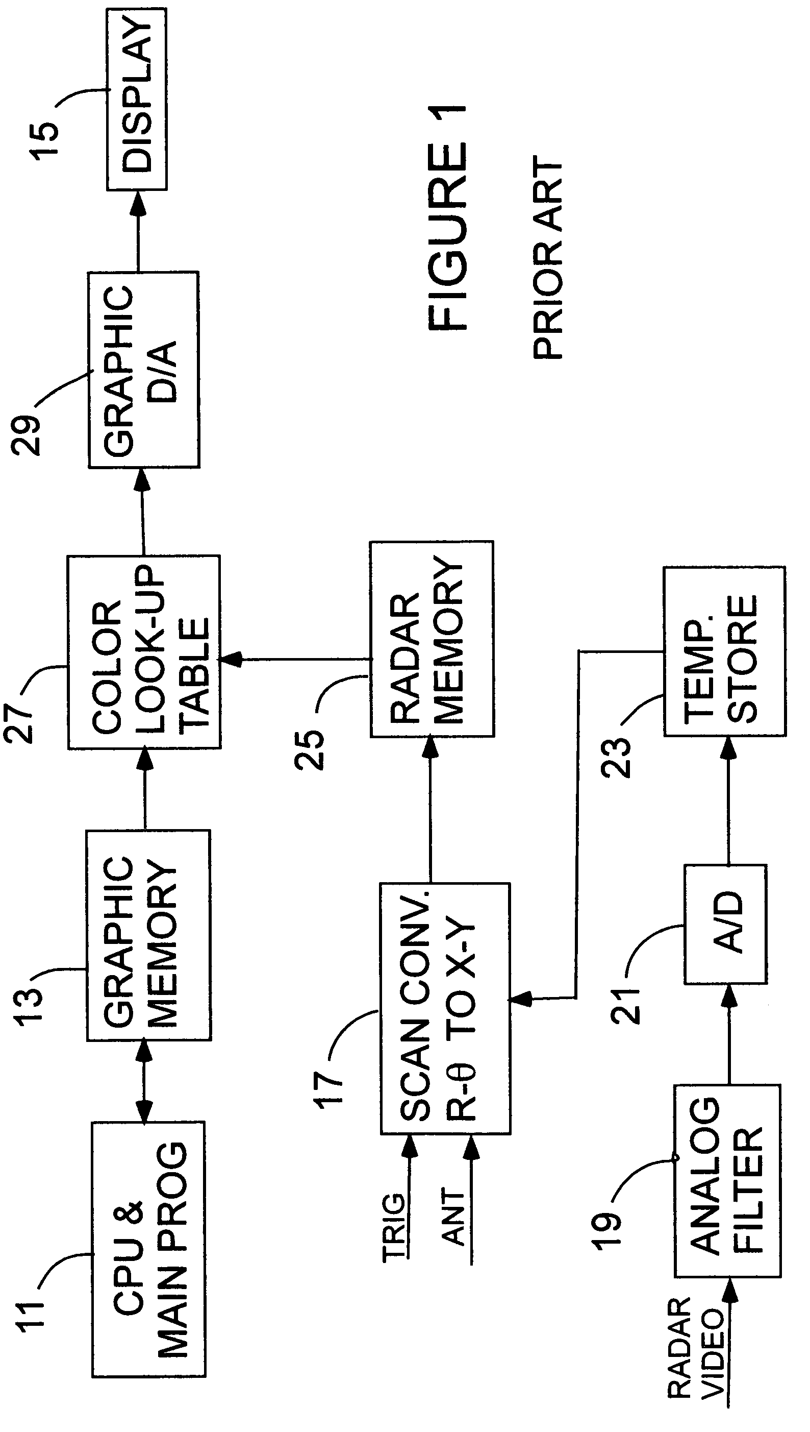
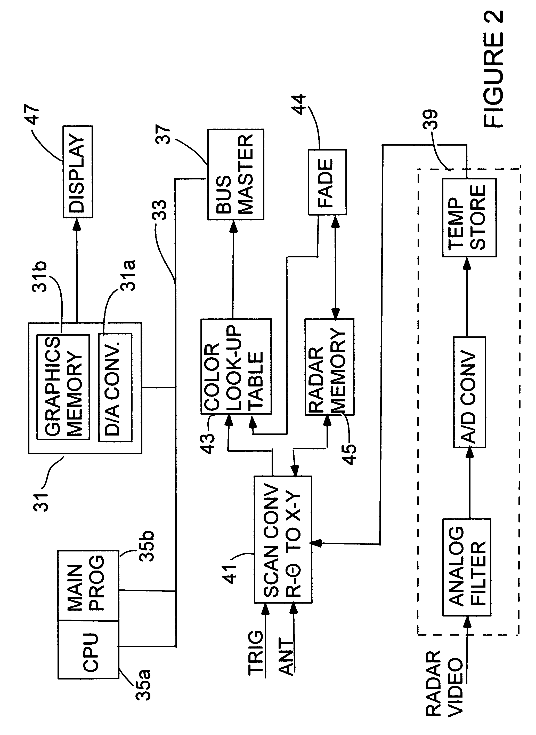
[0019]Refer now to FIG. 1. In a radar and graphics display system of the prior art a CPU and main program 11 generate graphics and text that are written to a 4 bit per pixel graphics memory 13. Graphics memory 13 is a dual port type that lets the CPU talk to memory at one port while the other port provides refresh data to a display monitor 15.

[0020]Radar video signals are coupled to a scan converter 17 as are a synchronizing trigger and an antenna pointing direction signal. This information is a rho-theta format. Rho, range, is determined by time from the trigger while theta, azimuth, is obtained from a signal coupled from an antenna drive system. Radar video is processed through an analog filtering circuit 19 and then converted to a digital data stream by an analog to digital converter (A / D) 21. This data stream of digital video is placed in a temporary store 23 for use by the scan converter 17. Temporary store 23 contains sample data for a single value of theta and rho values, for...


PUM


Abstract

A scan conversion is provided which allows the scan converter to work with data in its most convenient format in a radar memory. A displayable image is mirrored to a graphics memory simultaneously with the write portion of the radar memory of the scan conversion process. On every write to the radar memory, radar data is simultaneously converted to associated colors by indexing a color look-up table and writing the indexed color to the graphics memory. A simulated phosphor decay for the display is provided by decreasing the intensity of each pixel in the radar memory once each antenna scan and similarly decreasing the intensity of data in corresponding locations in the graphics memory to simulate the decay of a phosphor coated screen in a CRT display. The signals in the graphics memory are coupled to a display at a rate that simulates a display on a phosphor coated screen.

Description

[0001]The priority benefit of Provisional Application No. 60 / 517,308 filed Nov. 4, 2003 is claimed by this application.BACKGROUND OF THE INVENTION[0002]1. Field of the Invention[0003]The invention pertains to the field of display systems, and more particularly to a PC platform display system simulating a long persistence phosphor display.[0004]2. Description of the Prior Art[0005]There is a need to emulate a long persistence phosphor to improve digital radar displays. The realization of this improvement presents several problems:[0006]Efficient processing of data during scan conversion requires the data to be in a 4 to 8 bits per pixel and a 1024 by 1024 pixel bitmap format, while the display format must be in a 32 bit per pixel true color. Present host computers are not capable of converting a 1024 by 1024 bitmap to a 32 bit true color at a fast enough rate for a radar display.[0007]The scan conversion requires read-modify-write cycles to memory at a very high rate that is not prac...

Claims


Application Information

Patent Timeline
IPC IPC(8): G01S7/04G01S13/00G01S7/298H04N7/01
CPCG01S7/298G01S7/10
Inventor BEAZELL, THOMAS G.
Owner NORTHROP GRUMMAN SYST CORP
Why Eureka
Try Eureka