Light emitting device and apparatus using the same

a technology of light emitting devices and light emitting devices, which is applied in the direction of lighting and heating apparatus, lighting applications, instruments, etc., can solve the problems of difficult to increase the area of such light emitting devices, and reduce the usability of ligh

Inactive Publication Date: 2007-01-09
ORMON CORP
View PDF12 Cites 117 Cited by
  • Summary
  • Abstract
  • Description
  • Claims
  • Application Information

AI Technical Summary

Benefits of technology

[0026]In addition, the components of the present invention...

Problems solved by technology

According to the light emitting device, although the light emitted from the LED chip forward passes through an interface of the mold resin and directly emitted from the light emitting device, the light emitted from the LED chip in the slanted direction is totally reflected by the interface of the mold resin or scattered in its case, which becomes loss and lowers light usability.
In addition, it is difficult to increase an area in such light emitting device.
Thus, according to the conventional light emitting device 1, since a ring-shaped dark part (dark ring) having a wide width is generated when viewed from the front fac...

Method used


Image

  • Light emitting device and apparatus using the same
  • Light emitting device and apparatus using the same
  • Light emitting device and apparatus using the same

Examples


first embodiment

(First Embodiment)

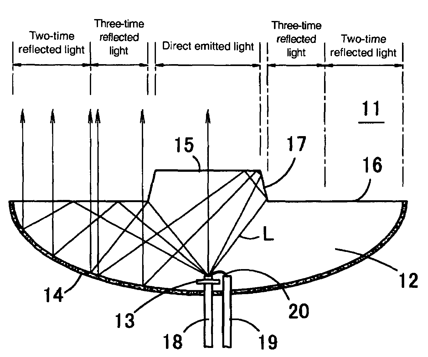
[0064]FIG. 4 is a perspective view showing a structure of a light emitting device 11 according to an embodiment of the present invention, FIG. 5A is a sectional view thereof, and FIG. 5B is a view showing luminance distribution at the front face of the light emitting device 11. A mold part (light guiding member) 12 in the shape of almost a dish is molded with a light transmitting material having high refractive index, such as a transparent resin in the light emitting device 11. As the light transmitting material constituting the mold part 12, a light transmitting resin such as an epoxy resin or an acrylate resin may be used or a glass material may be used. A light emitting element 13 such as an LED chip or a lamp is die bonded on a stem formed on an end of one lead terminal 18, and the light emitting element 13 is electrically connected to the other lead terminal 19 by a bonding wire 20. The light emitting element 13 and the ends of the lead terminals 18 and 19 are...

second embodiment

(Second Embodiment)

[0088]FIG. 8A is a perspective view showing a structure of a light emitting device 21 according to another embodiment of the present invention, and FIG. 8B is a sectional view thereof. According to the light emitting device 21, a flat face 22 for totally re-reflecting the light L which was totally reflected by a slanted total reflecting portion 17 is formed at a peripheral part of the direct emitting portion 15, and a lens face 23 is formed in a region other than the peripheral part of the direct emitting portion 15.

[0089]According to the embodiment shown in FIG. 4, since the direct emitting portion 15 is the flat face, the light L emitted from a region other than a central part of the direct emitting portion 15 is emitted in the direction slanted from the central axis. However, according to the light emitting device 21 of this embodiment, the region required for totally re-reflecting the light L which was totally reflected by the slanted total reflecting portion ...

third embodiment

(Third Embodiment)

[0091]FIG. 10 is a perspective view showing a structure of a light emitting device 24 according to still another embodiment of the present invention, FIG. 11A is a sectional view thereof and FIG. 11B is a graph showing luminance distribution at the front face of the light emitting device 24. According to the light emitting device 24, a ring-shaped groove 25 is formed between a circular and flat direct emitting portion 15 and a flat total reflecting portion 16 formed around it, a total reflection face (third total reflecting portion) 26 is formed on a bottom face of a groove 25 and a slanted total reflecting portion 17 is formed by slanting its inner peripheral sidewall face. In the illustrated example, the direct emitting portion 15 and the total reflecting portion 16 are formed on the same plane and the direct emitting portion 15 is positioned at the same height as that of the total reflecting portion 16. However, it does not matter even if the direct emitting por...


PUM


Abstract

A mold part formed of a light transmitting material having a high refractive index is molded in a concave-shaped reflecting member, and a light emitting element such as an LED chip or the like is inserted in the center of the mold part. A circular direct emitting portion is provided at the center of a front face of the mold part, a ring-shaped total reflecting portion is provided around it, and a slanted total reflecting portion is provided between the direct emitting portion and total reflecting portion. Thereby, the uniformity of front face luminance with a simple structure in a light emitting device provided with a reflecting member on a back face of a mold part is improved.

Description

BACKGROUND OF THE INVENTION[0001]1. Field of the Invention[0002]The present invention relates to a light emitting device and an apparatus using the light emitting device, and more particularly, to a light emitting device and a light emitting apparatus using an LED (light-emitting diode) chip or the like, and an apparatus such as a luminaire, a display unit or the like, which uses the light emitting device.[0003]2. Description of the Background Art[0004]As a small-type light emitting device, a cannonball-shaped LED in which an LED chip is sealed in a transparent mold resin is well known. According to the light emitting device, although the light emitted from the LED chip forward passes through an interface of the mold resin and directly emitted from the light emitting device, the light emitted from the LED chip in the slanted direction is totally reflected by the interface of the mold resin or scattered in its case, which becomes loss and lowers light usability. In addition, it is di...

Claims


Application Information

Patent Timeline
IPC IPC(8): G09G3/32F21S8/04F21S8/00F21S8/10F21V5/04F21V7/04F21V7/09F21Y101/02H01L33/50H01L33/54H01L33/56H01L33/60H01L33/62
CPCH01L33/54H01L33/60F21S48/215F21W2111/00H01L2224/48247H01L2224/48091H01L2924/00014F21S43/14H01L2924/181H01L2924/1815H01L2924/00012
Inventor HOMMA, KENJIAYABE, TAKAHIROKIYOMOTO, HIRONOBU
Owner ORMON CORP
Why Eureka
Try Eureka