
Modulation of sidewalls of servo sectors of a magnetic disk and the resultant disk

a technology of magnetic disks and sidewalls, applied in the field of magnetic disk drives, can solve problems such as the disruption of the fly height of the head

Inactive Publication Date: 2007-01-09
WD MEDIA
View PDF24 Cites 104 Cited by
  • Summary
  • Abstract
  • Description
  • Claims
  • Application Information

AI Technical Summary

Benefits of technology

This solution allows for precise head positioning without disrupting fly height and separates data and servo signals effectively, enhancing thermal stability and data integrity in high-density recording.

Problems solved by technology

According to this article, discrete track media improve the side writing and side reading phenomena which would be serious problems in conventional continuous magnetic film media at very high track densities.
Also, pre-formatted servoing information may cause a disruption in fly height of a head as it flies over a preformatted area on a DTR disk.

Method used


Image

  • Modulation of sidewalls of servo sectors of a magnetic disk and the resultant disk
  • Modulation of sidewalls of servo sectors of a magnetic disk and the resultant disk
  • Modulation of sidewalls of servo sectors of a magnetic disk and the resultant disk

Examples


Embodiment Construction

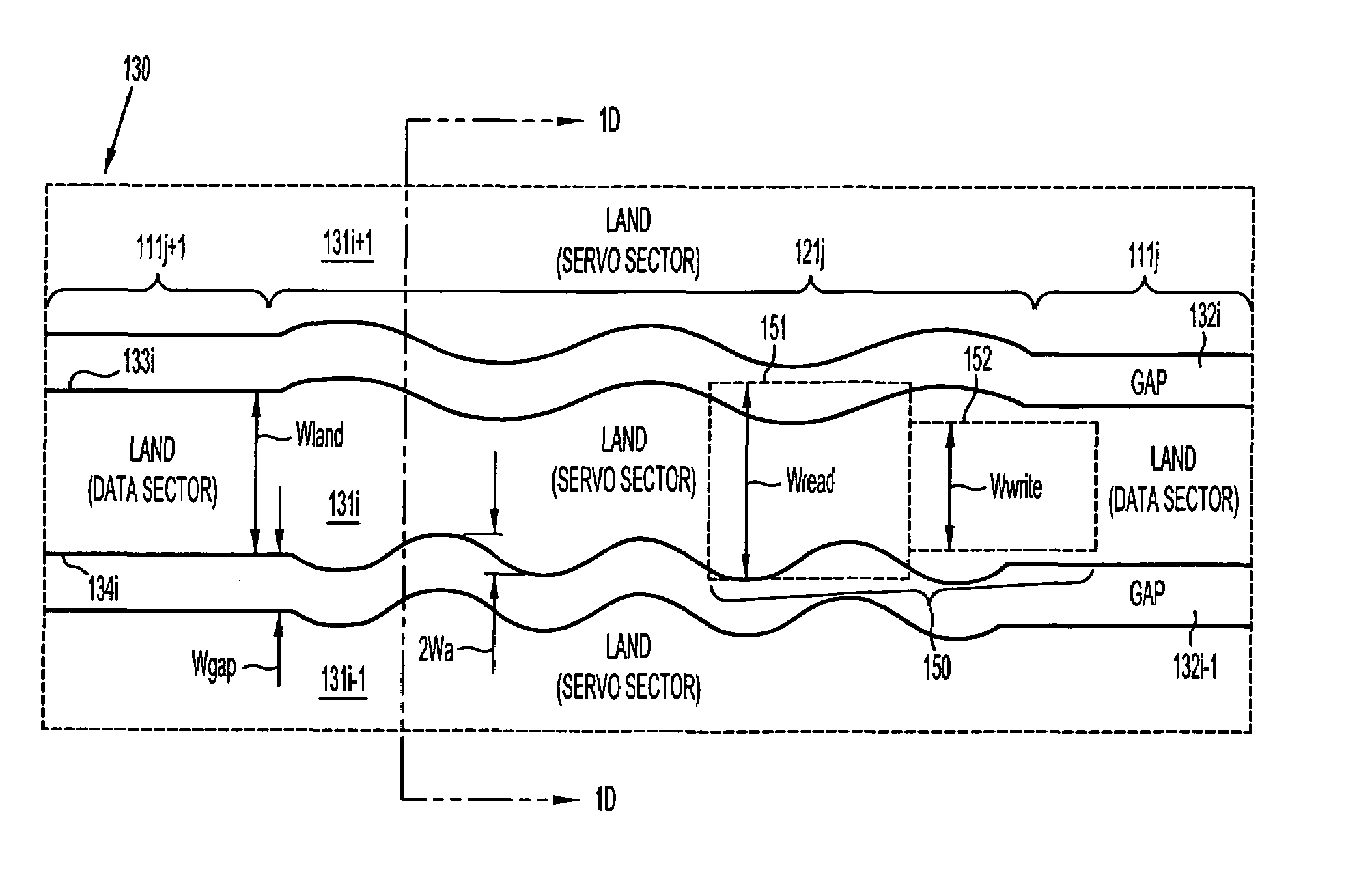
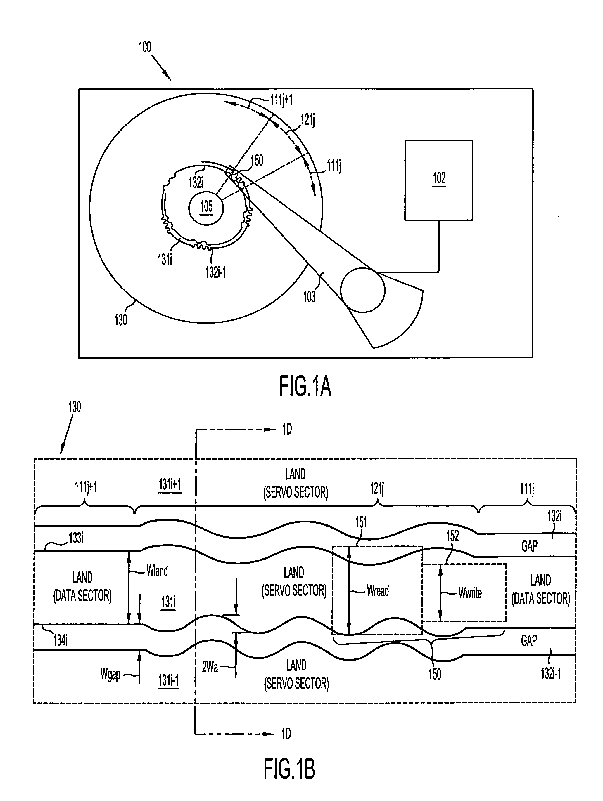
[0024]A discrete-track-recording disk 130 (FIG. 1A) has a number of areas that hold a signal (called “lands”) 131i−1, 131i, 131i+1 (see FIG. 1B) that are separated from each other by areas (called “gaps”) 132i−1 and 132i that inhibit storage of data. A land area 131i is also referred to as a “track.” Note that gap area 132i is implemented in many embodiments of disk 130 by a trough which is a physically recessed area (relative to land area 131i) as shown in FIG. 1D, although in alternative embodiments gap area 131i is implemented as an area that is at the same elevation as the land area but contains a material that cannot be magnetized. The unmagnetizable material may be created, in disk 130 of such alternative embodiments, by ion implantation.

[0025]Each land area 131i (FIG. 1A) in disk 130 is formed in multiple sectors, such as servo sector 121j (FIG. 1A) that is used in positioning a head relative to the disk. Servo sector 121j is located between two data sectors 111j and 111j+1 w...


PUM

PropertyMeasurementUnit
trough depth Dtaaaaaaaaaa
rotationaaaaaaaaaa
frequencyaaaaaaaaaa

Abstract

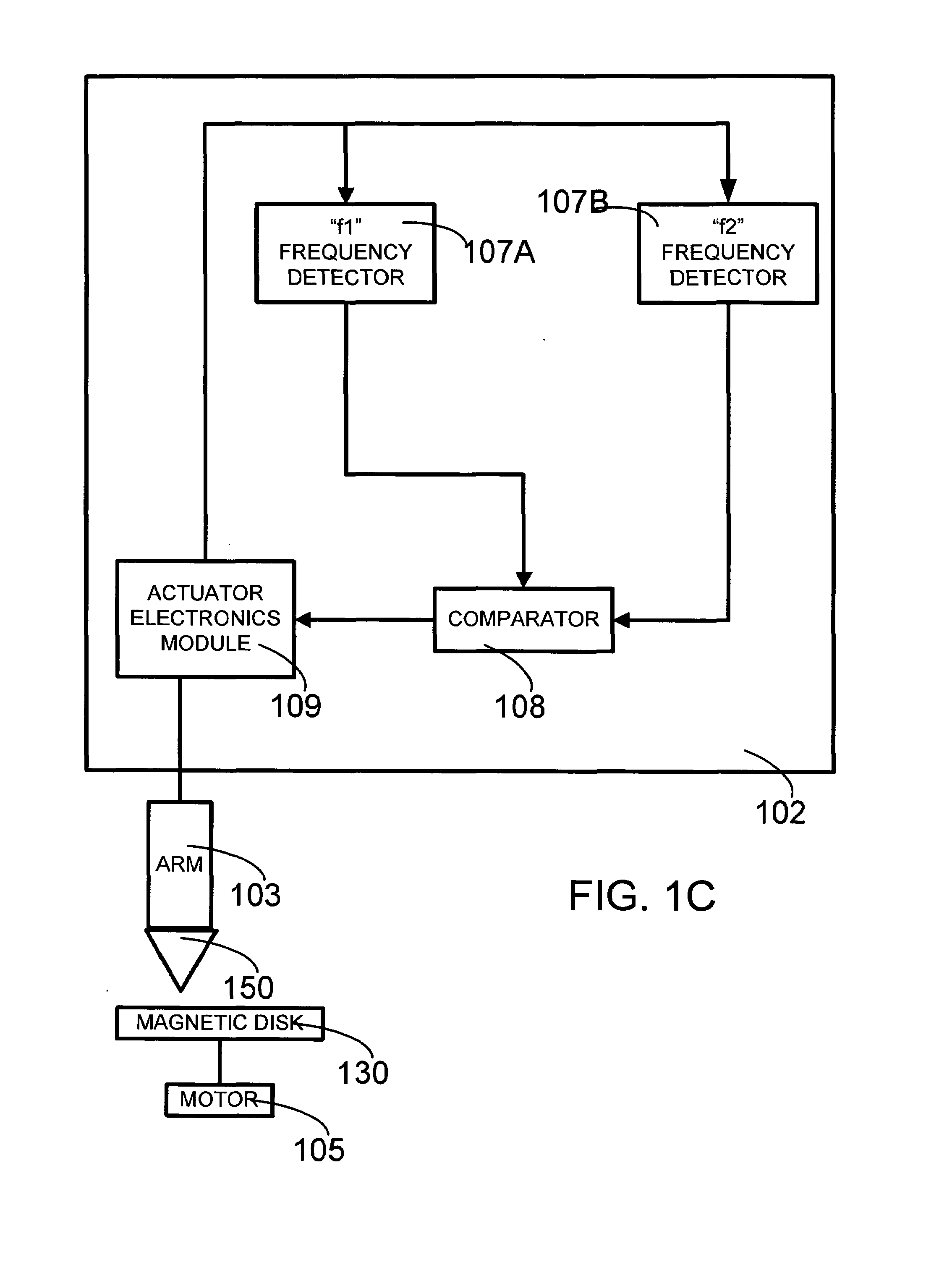
A discrete-track-recording (DTR) disk (also called “patterned” disk) has a sectored servo formed by modulation of its sidewalls in a predetermined manner, whereas sidewalls of data sectors are not modulated in this manner. Each servo sector has two side walls that are each respectively modulated in two different ways. Hence, a readback signal from a given servo sector contains components of each of the two different modulations, even in case of “DC” erase initiation. Therefore, the just-described modulated servo sectors eliminate servowriting. Moreover, data signals are read without filtering the modulation, because data sector sidewalls are not modulated.

Description

CROSS-REFERENCE TO RELATED APPLICATION[0001]This application is a related to U.S. patent application Ser. No. 10 / 077,200 filed by Michael McNeil et al. on Feb. 15, 2002 entitled “Patterned Medium” (published as US 20030179481 on Sep. 25, 2003), which is incorporated by reference herein in its entirety.BACKGROUND[0002]1. Field of the Invention[0003]The invention relates to the field of magnetic disk drives, and more specifically, to patterned magnetic disks (also called “discrete track recording” disks or DTR disks) used in disk drive systems.[0004]2. Related Art[0005]Discrete track recording (DTR) disks or patterned magnetic disks are known in the prior art. See, for example, an article entitled “Beyond discrete tracks: Other aspects of patterned media” by S. E. Lambert, I. L. Sanders, A. M. Patlach, M. T. Krounbi, and S. R. Hetzler, published in Journal of Applied Physics Vol 69(8) pp. 4724–4726. Apr. 15, 1991. Specifically, this article states that the surface of a thin-film disk ...

Claims


Application Information

Patent Timeline
Patent Type & Authority Patents(United States)
IPC IPC(8): G11B5/09
CPCB82Y10/00G11B5/59633G11B5/82G11B5/743G11B5/6011
Inventor WACHENSCHWANZ, DAVIDTREVES, DAVID
Owner WD MEDIA
Learn More